Introduction:
The purpose of this document is to highlight the proper installation and end-to-end testing of the fiber plant (aka, fiber backhaul) that is used to optically connect the analog fiber master unit to the analog fiber remote unit(s). Improper fiber installation and testing will result in increased system integrator troubleshooting and installation costs, and cause communication performance issues between the fiber master and fiber remote DAS equipment. It is imperative that proper cleaning techniques and end-to-end fiber testing on the installed fiber plant (which includes patch panel(s), patch cable(s), fusion splice(s), and connectors) are performed.
Fiber Plant:
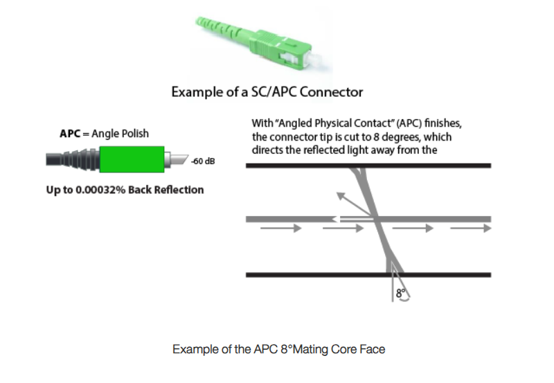
For an analog fiber DAS solution, the fiber plant must be deployed with Single-Mode fiber and terminated with SC/APC (Angle Physical Contact or Angle Polished Connector) connectors.
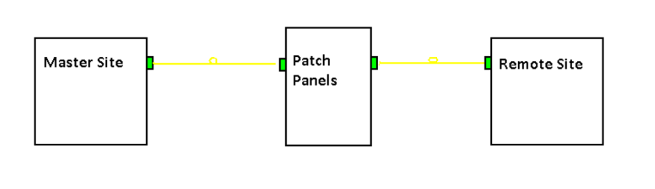
Block Diagram of a Fiber Plant
Once the fiber plant is installed, the system integrator will be required to perform optical test measurements to ensure that the fiber plant is within operating specifications prior to the installation of any fiber DAS equipment. The quality of the optical path must be checked throughout the entire length of the fiber plant to determine optical reliability (aka, end-to-end testing). All fiber connectors, including fusion splicing, must be certified to meet industry standards. An Optical Time Domain Reflectometer (OTDR) is used to test and certify the optical performance of the fiber plant by identifying reflection points throughout the entire length of the fiber path. Any reflections will degrade the linearity of a fiber optic link and introduce noise, thus why it is important to confirm the fiber is working within tolerance. It is best to keep all discrete reflections to <60 dB.
Differences in SC Fiber Connectors:
The SC/APC connector can be identified by a green connector boot and square body. The fiber end is angle polished to 8° and offers a large surface area of contact between the mating connectors. The APC improves coupling efficiency and minimizes connector back reflection or return loss characteristics, thus keeping the return loss below <60 dB.
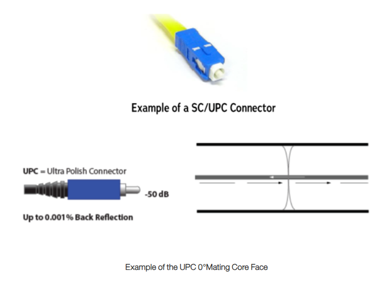
The SC/UPC connector looks very similar but is the incorrect connector type when it comes to analog fiber DAS deployment, it is generally identified by a blue square body and uses an ultra physical contact (UPC) of 0°.
WARNING: This type of connector must not be used anywhere within the fiber plant network, the insertion loss (reflectance) is too high and will disrupt the communications between fiber master and fiber remote equipment and preventing the system from being commissioned.
Avoiding Fiber Contamination and Creating Reliable Fiber Connections:
There are 3 basic principles that are critical to achieving an efficient and reliable fiber optic link:
· Optimal Core Alignment
· Physical Contact
· Clean Connector Interface
Current connector design and manufacturing techniques have eliminated most of the challenges to achieving core alignment and physical contact. What remains challenging, is maintaining a clean connector interface.
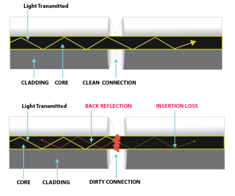
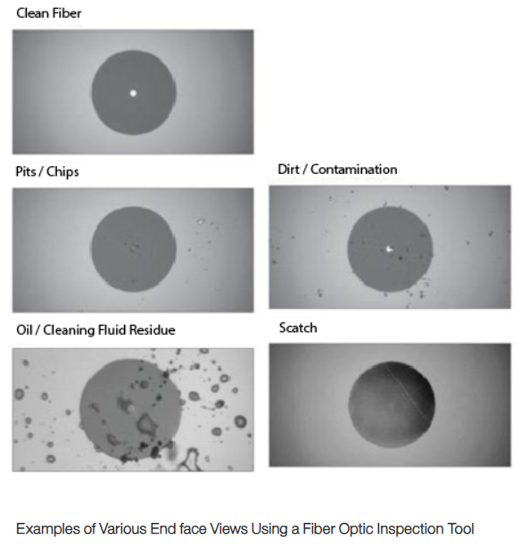
Faulty connections and contamination are the number one source of troubleshooting in optical networks. A single particle mated into the core of a fiber can cause significant back reflection (Return Loss), insertion loss, and ultimately damage equipment. Clean optic fiber components are imperative to the quality of optical performance within any fiber link. It is the most basic and important procedure to be carried out before mating together any optic fiber assembly. Any contamination within the fiber connection can cause failure of that component and even failure of the entire system. Thus, clean components are a necessity for quality connections with optic fibers. When cleaning fiber components, the procedure must be followed correctly and precisely with the goal of eliminating any dust or foreign contamination. A clean component will connect properly; however, a dirty component may transfer contamination to the mating connector or may even damage the optical contacts. Remember components are not guaranteed to be clean on receipt from the supplier. Any foreign object partially or completely blocking the fiber core will result in strong back reflections and cause the laser system to become unstable.
For example, a 1-micron (0.001 mm) dust particle on a single-mode core can block up to 1% of the light (a 0.05dB loss), a 9-micron (0.009 mm) speck can completely block the fiber core.
Examples of contamination:
· Oils – frequently from human hands
· Film residues – condensed from vapors in the air
· Powdery coatings – left after water or other solvents evaporate away
Particles trapped between fiber core mating faces can scratch the glass surfaces or cause an air gap which can misalign the fiber mating cores, thus degrading the optical signal path.
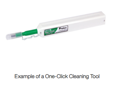
Using a “one-click” cleaning tool on each fiber connector before mating the connection points will ensure that the fiber is clean.
The only way to know if the fiber is truly clear of any contamination, or if it is damaged, is by using a fiber optic inspection tool.
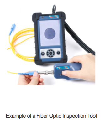
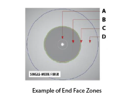
The fiber optic inspection tool allows you to visually inspect the four zones of the fiber connector:
A. Core Zone
B. Cladding Zone
C. Adhesive/Epoxy Zone
D. Contact/Ferrule Zone
Conclusion:
Visual inspection and cleaning are the only way to determine if fiber connectors are truly reliable before mating them. End-to-End testing with an OTDR, is the only way to know that the entire length of the fiber is within specification and ready for equipment deployment and commissioning. By implementing a simple, yet important, process of proactive visual inspection, cleaning and OTDR testing, poor optical signal performance and potential equipment damage can be avoided.

