In the realm of radio communication, establishing reliable connections is crucial for seamless data transmission and effective communication. However, issues often arise due to improper setup of the Bi-Directional Amplifier (BDA) gain, resulting from a lack of understanding of accurate link budget calculations. This technical brief addresses this critical concern by focusing on the essential components of the link budget. By comprehending the concepts and calculations related to free space path loss, cable loss, BDA gain, passive losses in the Distributed Antenna System (DAS) field cabling, free space path loss between the field antenna and AHJ radio, and the output power of the AHJ’s radio, users will gain the knowledge required to ensure optimal radio communication performance.
Gathering Essential Information before Site Commissioning:
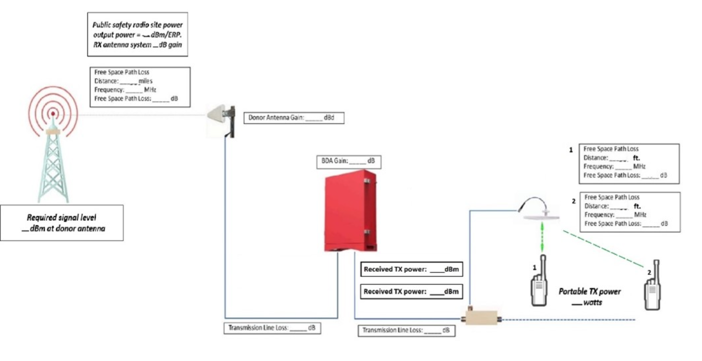
Before heading to the site for BDA commissioning, certain information needs to be collected to ensure accurate link budget calculations. This includes Donor site information and key details about the building. Information, such as distance to Donor site and expected transmit power from the BDA, can be gathered from maps or online resources. Additional details, such as separate UL and DL gains of antennas and the Effective Radiated Power (ERP) of the donor site, directly from the AHJ. Since permission from the AHJ’s licensee is necessary to activate the BDA, engineers should have no issue requesting this information.
Engineers should also gather crucial information about the donor antenna’s gain and the donor cable loss. The gain of the donor antenna represents the amplification of the signal received, and it plays a significant role in accurate link budget calculations. Additionally, the donor cable also introduces losses into the system. On average, the donor cable loss is approximately 2 dB for every 100 feet of cable, with an additional 1 dB of loss due to connectors and jumpers. Considering these values allows for a more precise assessment of the link budget and ensures optimal system performance.
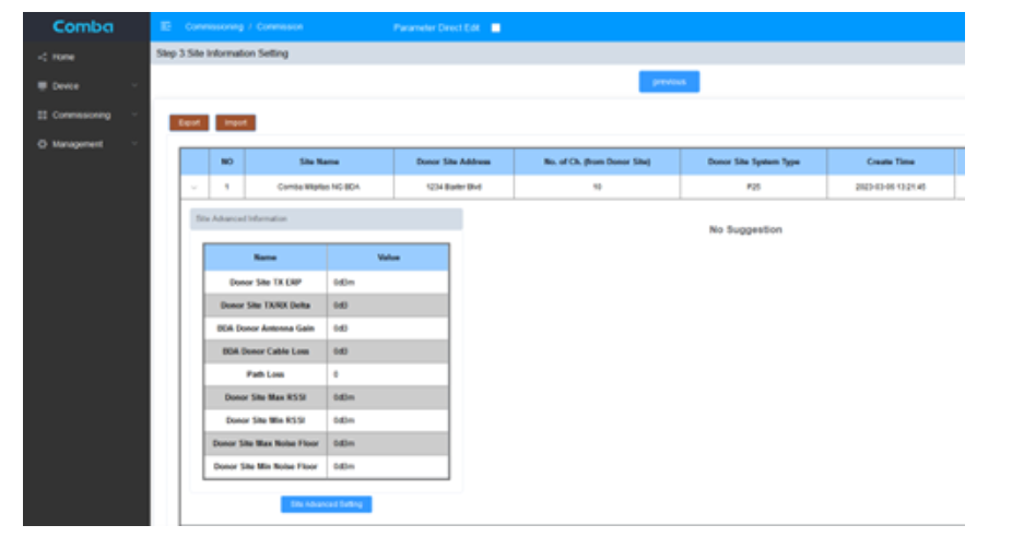
Comba’s commissioning process in the NG BDA provides a convenient means to track and organize this information effectively, ensuring that engineers have all the required data for accurate link budget calculations. By incorporating all gains and losses in the signal path between the donor site and BDA, engineers can make informed decisions and optimize the performance of the radio communication system.
Calculating Free Space Path Loss and Passive Losses in the DAS Field:
During the BDA commissioning process, Comba’s NG BDA provides a streamlined approach for calculating the free space path loss and passive losses in the DAS field. Engineers can utilize a signal generator in the UL Testing of the NG BDA to measure passive losses. By walking around the building under different antennas and identifying areas with weak signal reception, accurate path loss calculations for the weakest and strongest signals in the building can be obtained. Comba’s NG BDA sets a minimum signal strength to ensure valid recordings, filtering out weaker signals. Additionally, manual options, such as using a spectrum analyzer connected to the cable going to the mobile transmission port of the BDA, can be employed to measure signal strengths.
FSPL (in dB) = 20log₁₀(d) + 20log₁₀(f) + 20log₁₀(4π) – 105.4
- d is the distance between the transmitter and receiver in miles.
- f is the frequency of the signal in Hz.
During the manual method of calculating passive losses in the field using a spectrum analyzer, it is important to note that two people are required for this process. This requirement arises from the limitations of using a “minimum hold” function on the spectrum analyzer.
When one person walks around the building with the signal generator, the minimum hold function captures the weakest signal encountered. However, if the person walking turns off the signal generator or enters an area with no coverage by the DAS, the minimum signal value recorded by the spectrum analyzer will drop to the noise floor. This situation prevents accurate measurements of the weakest signal. Thus, a second person is needed to manually record the weakest signal strength.
After calculating the full path loss on the passive DAS, engineers can then employ the FSPL formula to calculate the path loss of the passive components and remove the loss between the signal generator and DAS antenna. This approach enables a more accurate assessment of the passive losses within the DAS.
Determining BDA Gain and Commissioning the System:
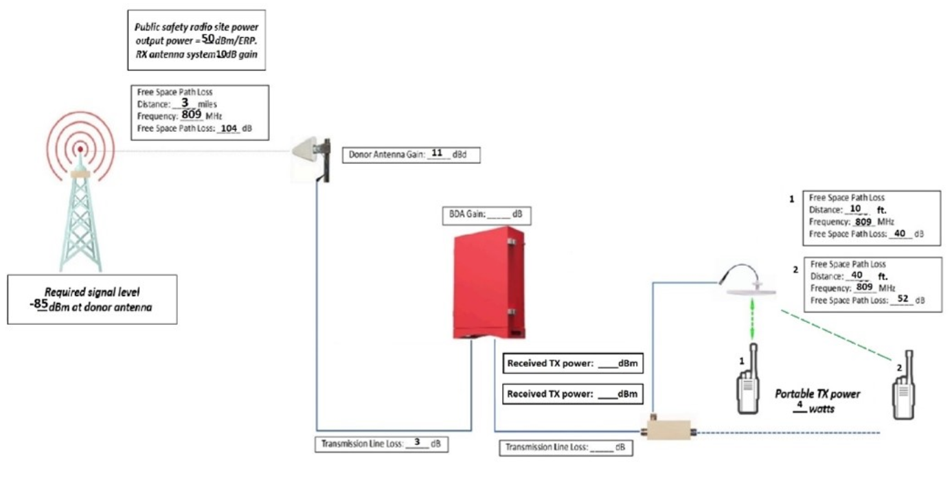
With all the collected information, engineers can effectively calculate the appropriate BDA gain settings to ensure the tower receives the required signal strengths and comply with FCC regulations for DAS output. The NG BDA commissioning guide suggests gain values based on the entered information at the end of the guide. However, it is essential to double-check the math and validate the link budget calculations to ensure accurate commissioning. Below uses information from the picture to determine the UL gain based on calculated FSPL between the Donor site and donor antenna. True loss may be greater due to lack of line of sight between objects.
43dBm + x dB – 3dB + 11dBd – 104dB + 10dB = -85dBm @ Tower
X = 44dB of gain
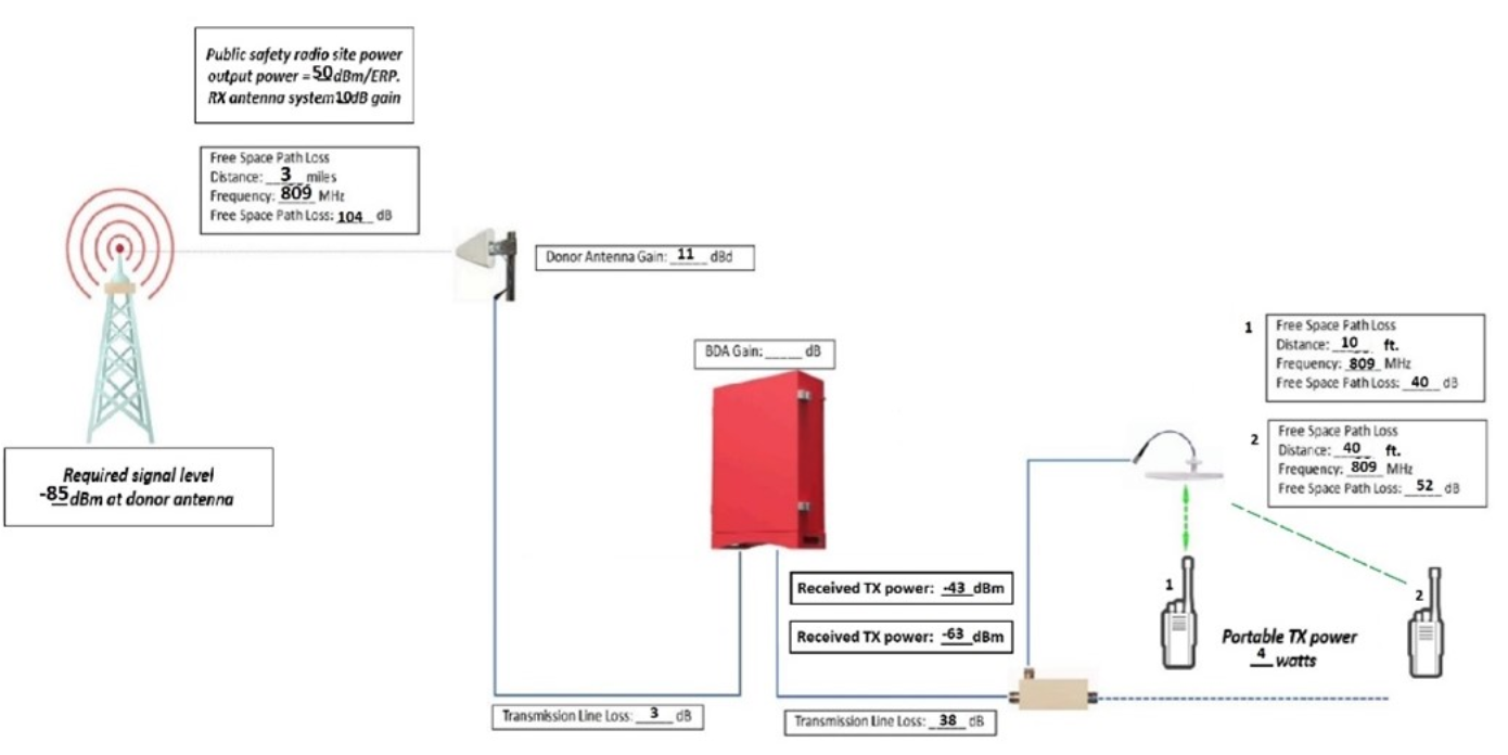
-63dBm + x dB – 3dB + 11dBd -104dB + 10dB = -85dBm @ Tower
X = 64dB of gain
UL gain to be set to 64dB with channel power output of BDA limited to 3dBm
Conclusion:
In conclusion, accurate link budget calculations are vital before completing the commissioning process and activating a radio communication system. Comba’s NG BDA simplifies this process by assisting engineers in collecting and organizing essential information. However, it is important to note that the accuracy of the recommendations depends on the information entered. To ensure precise and reliable system commissioning, it is recommended that engineers doublecheck the link budget calculations themselves.
Furthermore, accurate link budget calculations are crucial for complying with regulatory codes such as FCC Part 90.219. This regulation imposes limitations on the total system output power back to the tower, including the donor antenna, which is restricted to 5W. By accurately calculating the link budget, engineers can ensure compliance with such regulatory requirements.
Comba’s NG BDA provides comprehensive support in meeting regulatory codes, optimizing link budget calculations, and ensuring compliance with power output limitations. Its value lies insimplifying the process and providing reliable results.