How to Perform a Manual Isolation Test on a Fiber DAS
Introduction:
Conducting the isolation test is one of the most important steps when commissioning a BDA or Fiber DAS solution. If the isolation test is not properly performed, it may result in DAS oscillation, which will damage BDA or Fiber BDA internal components and cause serious interference to the local Public Safety Network. This tech brief will discuss how to perform a manual isolation test specifically on a Fiber DAS solution.
Today, all of Comba’s 700/800MHz Public Safety DAS equipment comes with a built-in automatic isolation test, and should be used anytime DAS commissioning occurs, the passive DAS layout changes, the donor antenna type/location changes, or any additional remote units are added to a Fiber DAS solution.
Although the built-in software isolation test is a good to tool to use, sometimes it is necessary or even recommended to perform a manual isolation test, especially when you have interference from any external RF sources or equipment that may compromise or negatively impact the automatic test function.
Two Testing Procedures:
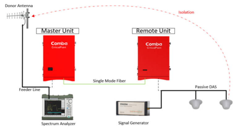
There are two options when performing a manual isolation test on a Fiber DAS solution. The first option would be applying the same procedures when measuring isolation on a BDA only passive DAS solution.
In this case, a CW test tone would be injected into the passive DAS antenna(s) at each remote location and then measure the test signal power at the donor cable/feed line. See Figure 1 example below.

Figure 1: Option 1 Manual Isolation Testing Procedure
In the above scenario, the below formulas would be used to calculate Isolation and Maximum Gain:
Isolation = TX Power – RX Power = +10dBm – (-105dBm) = 115dB
Max. Gain = Isolation – 20dB = 115dB – 20dB = 95dB

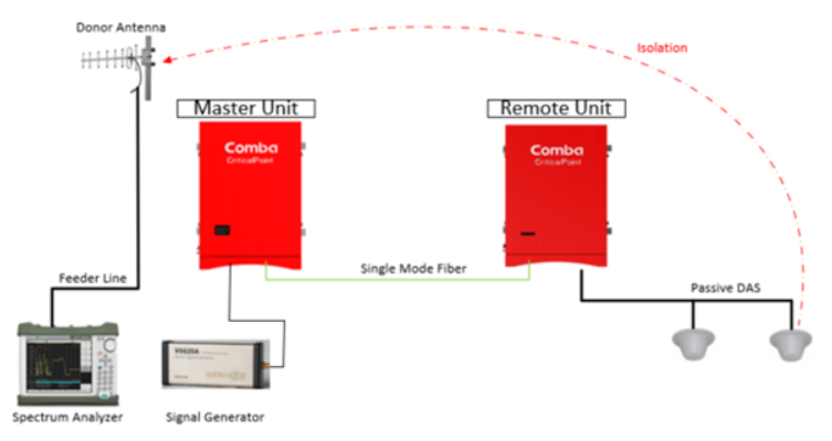
Figure 2: Option 2 Manual Isolation Testing Procedure
When using this procedure, it is important not to overdrive the Master Unit and activate the ALC/AGC circuits, thus, a lower TX input power must be used during this procedure.
The TX power should be less than or equal to the channel target output power of the fiber remote minus the gain. If your input power is too high, your measurements will be inaccurate, and may result in a lower isolation measurement and cause oscillation. The below formula is used:
TX Power <= Ch. Target power – Gain
Utilize the following steps to measure the Fiber DAS isolation on a Comba PS Fiber DAS product:
- With a Class A Fiber DAS, change the “ALC Mode” temporarily to Mode 1 in the Overview Page. This will provide a max output power (Target Power) of 33dBm with a single channel.
- Make sure to program your test frequency in the Master Unit filter page. In the case of a Class B system, ensure that your bandwidth includes the test frequency.

3. Set your DL System Gain to 95dBm on the test frequency (Master Unit 60dB DL Gain + Remote Unit 35dB DL Gain)

- Ensure that all the remotes have AC/DC power and are turned on, RF Switch in the Master Unit Overview Page and test frequency/filter is turned ON.
- Calculate your maximum TX input signal: Target Power – Gain = 33dBm – 95dBm = –62dBm
- Inject the TX signal into the Master Unit DT port with less than -62dBm. It is recommended that a lower than calculated input power in used, i.e. -65dBm ~ -70dBm. This way AGC/ALC is not activated.
- Measure the signal with your Spectrum Analyzer on the donor/feeder line that would normally feed the Master Unit DT port.
- Calculate the Isolation Delta, Isolation and Max Gain. See example below.
- Commission the system according to the isolation test results and other measurements.
- In the case of a Class A Fiber DAS system, be sure to change “ALC Mode” back to Mode 3, if required.
Calculation Example:
Standard Formula: Max Gain = Isolation – 20dB
Isolation Delta: TX Power – RX Power = (-70dBm) – (-91dBm) = 21dB
Isolation: Isolation Delta + Gain = 21dB + 95dB = 116dB
Max Gain = Isolation – 20dB = 116dB – 20dB = 96dB
OR
Max Gain = Gain – 20dB + TX Power – RX Power = 95dB – 20dB + (-70dBm) – (-91dBm) = 96dB
In this example, the Isolation Delta is more than the required 20dB, so Max Gain could be applied in the Fiber DAS.
Conclusion:
The second option is a quick and easy way to manually test the isolation of a Fiber DAS solution, but only provides the total system isolation for the Fiber DAS. This result includes all activated and connected fiber remotes. For troubleshooting low isolation issues and determining those areas, you may need to individually turn off fiber remotes in the software and repeat the testing procedure above. Please contact Comba Tech Support with any questions.

