When designing a public safety DAS for a single large building, sometimes you need more than just a single BDA to provide the coverage needed. While there is a choice between placing multiple BDAs into the same building or using a fiber DAS, the answer is clear that a fiber DAS is a much better choice.u need more than just a single BDA to provide the coverage needed. While there is a choice between placing multiple BDAs into the same building or using a fiber DAS, the answer is clear that a fiber DAS is a much better choice.
Multiple independent BDAs will be ignored in this paper – for an in depth discussion, please read the previous campus fiber DAS paper, which is more relevant to why multiple independent BDAs are not a good idea – especially within the same building, where they have more possibilities to cause interference with each other: https://combausa.com/pr/why-a-fiber-das-is-better-than-individual-bdas-for-campus-applications/
INSTALLATION SIMPLICITY
We will start by looking into the logistics of an installation:
| Fiber DAS | Cascaded BDAs | Split Donor |
Donor Antenna | Single Donor | Single Donor | Single Donors |
RF Transport | Fiber from MU to each RU | Coax from BDA to BDA | Coax from donor to each BDA |
Alarming | Can be done at a single point or at each RU | Must be done at each BDA | Must be done at each BDA |
Control | Single point of control for the entire system | Controlled individually at each BDA | Controlled individually at each BDA |
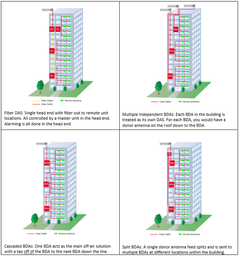
Installing a fiber DAS is the most similar situation here to having a single BDA – with a fiber DAS, there is a single donor antenna into a master unit. Fiber is used for essentially lossless RF transport between the master and the remote units. The single point that would need dry contact alarming is at the master unit, but if the jurisdiction requires, it can also be done at each remote unit individually. The system integrator would perform all commissioning activities at the master unit, so any changes that occur at the master would get pushed to the remote units.
In a cascaded BDA system, there is still a single donor antenna, but now there is coaxial cable that must be pulled between each BDA. At each BDA output, signal is tapped off the main feed and transported to the next BDA. Care must be taken to ensure you meet the link budget as designed. Any RF changes must be made and double checked on each BDA in the system – as the name implies, if you make a change, it has a cascaded affect, so the user will need to be constantly going between IDF closets to take measurements and make adjustments. In the cascaded BDA scenario, alarming must be done at each BDA individually, so each BDA will require a full set of dry contact alarms – which also necessitates multiple long runs of alarm cables back to the FACP.
In a split donor antenna system, there is a splitter at the donor antenna with an individual coaxial cable run to each BDA. When designing for a large building, this might mean that an individual coaxial cable run from the donor antenna could be hundreds or thousands of feet long – either requiring 7/8” cable or making signal strength requirements unachievable. Similar to the cascaded BDA system, alarming must be done at each BDA individually. However, now each BDA will act almost as an independent system, so while the system integrator must go to each BDA and commission it separately, there is not a cascaded affect when making changes to just one of the BDAs.
CASCADED BDA SOLUTION (AND WHY TO NOT USE THIS!)
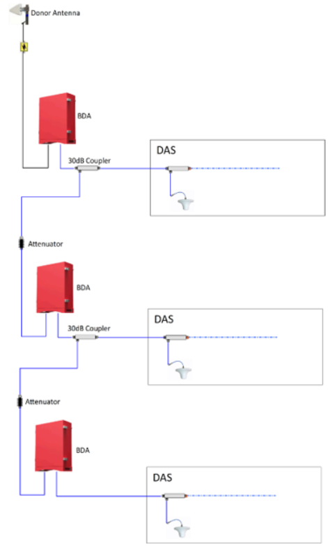
With a cascaded BDA design, we have an obvious problem that should prohibit us from ever using this approach: cascaded noise. The figure below shows a sample cascaded BDA system with 3 BDAs. At the output of each BDA is a 30dB directional coupler, with the coupled port going on to the next BDA down the line. At the input to the next BDA there would be an attenuator of appropriate value, based on cable length and link budget.
Let us look at what the uplink noise would be in this example:

Assuming a perfect setup and that UL noise rise = UL gain + noise figure, after 3 BDAs we go from a -47 dBm noise power output to a -35 dBm noise power output. This is a 12dB rise that makes our signal to noise ratio 12dB worse (in addition to reaching the tower at a 12dB higher noise floor).
This is a perfect scenario that assumes that noise power is related to the BDA gain – in many digital BDAs, noise power is related to maximum BDA gain. Let us look at this again assuming noise power is related to maximum gain rather than set UL gain. In this scenario, the gain is set to 80dB while the maximum BDA gain is 90db:
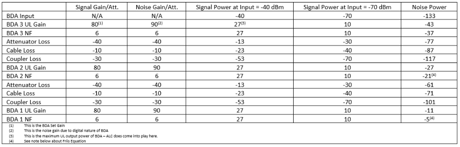
With all other assumptions the same, we see that the noise power out of the last BDA in line is -5 dBm, although our uplink signal power remains the same. This noise power rise is only 15dB weaker than our “low” signal strength output, which will almost certainly raise the noise floor at the donor site.
In reality, the uplink noise rise of a cascaded system will probably fall somewhere in between these two examples (the noise figure is not truly summed in this fashion – look up “Friis Formulas for Noise” for a deeper understanding), but even a small miscalculation in gain or loss can dramatically raise the noise floor (and then get cascaded through multiple BDAs).
In addition to the noise rise in a cascaded BDA system, time delay must also be studied. Let us assume we are in a jurisdiction that requires a Class A BDA and that each filter adds 20 microseconds of delay. Through 3 BDAs, that will add 60 total microseconds of delay, which is more than some radio systems can handle. Remember that this is 60 microseconds on uplink and 60 microseconds on downlink – this means the total roundtrip delay for this system is 120 microseconds. It depends on the digital system that is in place but many trunked systems would not be able to handle this amount of delay.
You would also have the issue of standing equidistant from antennas on 2 separate BDAs – if you have an equal power input to BDA3 and BDA2, then transmitting back to the antenna would give you the exact same signal strength twice, offset by 20 microseconds. This may lead to time delay interference (see https://combausa.com/pr/mitigating-tdi-time-delay-interference-on-public-safety-das-systems/ for more information on TDI).
Overall, it is highly recommended to not use cascaded BDAs in a single large building because a simple mistake that could be overlooked on a single BDA system can turn into a large noise rise through multiple uplink amplifiers.
SPLIT DONOR ANTENNA SYSTEM
An alternative to the cascaded BDA solution is using a single donor antenna and a passive splitter and splitting the donor signal to multiple BDAs. This solution is much better than cascading BDAs because you no longer have in-line amplifiers, but it still has many flaws.
Donor antenna isolation is problem number one with this solution. For a split donor antenna system, you have multiple BDAs running off a single donor antenna – you will need to manually test for isolation because a BDA on its own cannot detect oscillation between itself and another BDA’s service antennas. The isolation test will need to be done at the donor antenna through all the BDAs (so you must use a low power signal tuned to a passband frequency of the BDAs). BDAs have oscillation protection and shutdown, but this is typically programmed for a single BDA oscillating. If two separate BDAs are contributing to the oscillation, they may not detect a noise rise as oscillation and could continue transmitting as noise.
A second issue with a split donor antenna system is the simple problem of cable length – when a building is large enough, you may be running many hundreds or thousands of feet of coaxial cable between the donor antenna and the furthest BDA. Presuming approximately 2 dB of loss per hundred feet of coax this can add far too much loss to your link budget to enable an acceptable design and a working system.
FIBER DAS
For a single building that is too large for one BDA to cover, it is recommended to use a fiber DAS. A single master unit with a short run for the donor antenna ensures adequate off-air signal strength. Low loss fiber optic runs to the remote units ensure that no building is too large to cover. Flexible alarming ensures you can meet AHJ requirements for dry contact alarms. Uplink signal strength (and therefore noise) comes from a single output port on the master unit.
All changes to the system may be done directly from the master unit, so frequency settings, commissioning, isolation testing, and software upgrades are all done at one location.
A fiber DAS does have an additive noise floor based on the number of remote units, so the design needs to take this into account. However, the noise is only through the master unit, so one can easily measure and mitigate the noise produced from the system. With the simplicity of ensuring network compliance and meeting design criteria, the clear solution for public safety coverage in a large building is a fiber DAS.