FCC Definition
Part 90 Signal Booster Classifications
- Class A signal booster. A signal booster designed to retransmit signals on one or more specific channels. A signal booster is deemed to be a Class A signal booster if none of its passbands exceed 75 kHz.
- Class B signal booster. A signal booster designed to retransmit any signals within a wide frequency band. A signal booster is deemed to be a Class B signal booster if it has a passband that exceeds 75 kHz.
Translation
We in the Public Safety industry refer to the FCC’s definition of a Signal Booster device as a BDA, or Bi-directional Amplifier. A “Class A” BDA is the same as a Class A Signal Booster and “Class B” BDA is the same as Class B Signal Booster. Other common names for Class A devices are “Channelized”, or “Channel Selective” BDA’s. And for Class B devices, “Band Selective”, or “Broadband” BDAs.
Many of today’s BDAs are based on digital technology (software programable DSP) giving users much more flexibility in tailoring a BDA’s performance to a specific RF environment than its analog predecessors. Digital BDA’s allow the user to vary the passband bandwidth for each channel or a group of channels. The wider the passband window the more likely it is to pass frequencies that the BDA device is not authorized to pass and to cause interference to adjacent bands. All Class B Signal Boosters devices must be registered with the FCC so they can be managed and shut down if found to cause interference.
The FCC differentiates the Class A device from the Class B device by the bandwidth of the channel filter. If the channel filters are set to 75KHz bandwidth or narrower, then the device is classified and a Class A narrowband BDA. When the device channel filters are set for wider than 75KHz, the BDA is classified and a Class B broadband device.
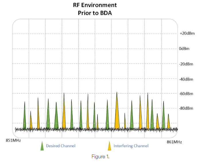
The following spectrum graphic shows a typical RF congested urban environment in the 800MHz SMR band before being received and amplified by the BDA. Notice that the band is populated with both the desired (licensed) channels and undesired, which we refer to as interference channels.
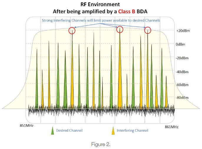
Next, we show how a Class B (broadband) BDA amplifies all frequencies within the operational pass band, which in this case is a 10MHz pass window between 851MHz and 861MHz. The green channels represent desired channels. Note how these channel frequencies are weaker than the interfering channels in yellow. In this example, which is indicative of real-world applications, the output power per channel is shared by all the frequencies appearing in the wide pass window; meaning the more channels, the lower the power per channel. What makes this scenario even worse is that the strongest channels will determine the BDA’s overall gain, and consequently the desired frequencies could actually receive 10-20 dB less gain and thus less power than the interfering frequencies. For this reason, Class B BDAs are more susceptible to changes in the RF environment, making communications less reliable and designing systems more difficult.
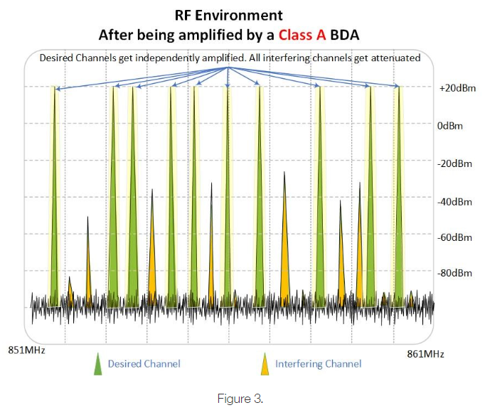
In Figure 3. We show that the Class A BDA amplifies and passes only discrete frequencies while all other (interfering channels) are attenuated and have little or no affect on the power available to the desired channels.
Which is better, Class A or Class B?
If you’ve read any of my previous tech briefs, you’re probably thinking I sound like a broken record when I say check with your AHJ. Your AHJ does have the final say. If your municipality has adopted code or has its own ordinance, your AHJ should be able to provide you with a copy or link to pertinent documentation. Some AHJs do not stipulate Class A or Class B device, but rather leave it to the System Integrator to meet the required performance criteria.
Price – Because Class A devices have more intelligence built-in and offer greater RF control they are generally higher priced than a Class B device. The price delta between Class A and Class B varies from vendor to vendor. However, roughly speaking, one can expect to pay about 30% more for a Class A device than a Class B with similar RF output power.
Setup – The Class B device may be easier to setup because it has fewer options. For example, some Class B devices may completely limit user from changing filter bandwidths. And for those devices that do allow user setup, it may be as simple as entering a start and stop frequency to define the pass window. Whereas, in a Class A device, all desired frequencies must be entered individually. Other user settings available in Class A devices but not typically available in Class B are features such as individual channel gain, squelch, and bandwidth options.
Reliability – From a product reliability standpoint, Class A & B have similar Mean-Time Between Failure (MTBF) ratings, however where they diverge is in their ability to maintain reliable system performance. As previously mentioned, Class A devices filter out undesired channels that could “rob” amplifier power from desired channels. Additionally, Class A devices have dynamic, or adaptive gain circuits that can absorb minor fluctuations in signal levels while maintaining stable output levels. Class B devices can experience significant fluctuations in output power based on channel loading in the wideband RF environment. These fluctuations can adversely affect in-building coverage and the reliability of first responder radio communications.
Site Noise – Class A devices have independent amplifier circuits that can remain silent until a radio is keyed from within the building, meaning only active channels are transmitted back to the donor site. This is in contrast to the Class B device where even with no radio traffic inside the building, the Class B device is always on, always amplifying noise.
With so many BDAs being implemented, mostly driven by code requirements, site noise has become a growing concern. The additive affect of noise generated by Class B BDAs and its detrimental affect to donor site sensitivity have led many AHJs to rethink their position on these broadband devices.
As a rule of thumb, we can expect a Class A device with properly setup squelch circuits to generate ~30dB less noise than a Class B device. Some Class A BDAs such as Comba’s CriticalPointTM Class A will go completely silent and generate no noise until radio traffic appears.
For more details on the ramifications of site noise, check out the following link:
https://combausa.com/en/tech-briefs/whats-all-the-fuss-about-uplink-noise
Near-Far Affect – The near-far affect as it relates to Public Safety DAS systems is when a portable is keyed near an indoor antenna and a second portable is keyed simultaneously at some distance X that represents halfway point between two antennas. When the near radio is keyed, it forces the Class B device to lower its gain to prevent saturation or destructive overload and consequently the radio positioned distance X away may not has sufficient gain available to communicate back to the donor site reliably. This near-far condition has resulted in code changes that now require a two-radio test process specifically targeting Class B implementations. Demonstrating compliance using a two-radio test helps ensure systems are designed properly with high antenna density to mitigate near-far potential.
This near-far condition is virtually nonexistent when using a Class A device because of the independent gain available to each channel, i.e., the near radio will have little or no affect on the far radios ability to reach the donor site.
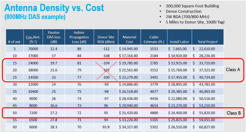
The higher density of antennas needed to comply with code in Class B applications can have a serious impact on your budget. The following table shows how using a Class A device for a 300,000 square foot building has a “sweet-spot” range of between 15 and 25 antennas. I have crossed out the “Donor Site RSSI (dBm)” portion of the Class A range because these levels are only applicable to Class B uplink calculations where reduced gain from the near condition limits the gain available for the far condition. Recall that the Class A devices have independent gain per channel and as such will generally have at least 30dB more gain available in the uplink path than a Class B device with gain being compressed by the near condition.
Now let’s look at the values in the Class B scenario which requires 50 antennas to meet the -95dBm target value back at the donor site receive equipment. With the doubling of antennas and couplers combined with additional cable and installation costs, any savings by choosing Class B over Class A is gone.
To better understand the uplink link budget and the math behind this near-far affect, refer to my March 2018 Tech Brief titled “Why code just made the donor antenna a rock star”, or click on the following link:
https://combausa.com/en/tech-briefs/why-code-just-made-the-donor-antenna-a-rock-star:
Scalability – Here is where the Class B device has a bit of an advantage over the Class A device. Class A devices can be programmed to accommodate most macro network channel counts, however if a frequency is added in the future and it falls outside the pre-programmed pass windows, then manual changes either by visiting the site or remote connection will be necessary. For Class B applications, any frequency appearing within the wide operational passband will get amplified. This is one of the two main reasons some AHJs prefer Class B devices. The other is delay, also known as TDI.
TDI – Which stands for Time delay Interference. This interference condition occurs when the direct signal from the donor site penetrates the building and rivals the amplitude of signals that are being distributed by the BDA DAS and that are delayed. A Class B device is a broadband device (Figure 2.) and has wide filters that typically introduce <10µsec of delay. A Class A device (Figure 3.) is a narrowband device with very sharp filtering and is designed to pass discrete frequencies. Consequently, Class A devices inherently introduce more delay, generally between 15µsec and 100µsec depending on the manufacturer of the equipment and the filter options available.
Municipalities using analog radio communications generally are un-affected by delay, however digital networks such as P25 Phase I and Phase II are more susceptible to delay issues. The amount of delay a radio can tolerate may vary by technology and manufacturer, but a general rule-of-thumb to minimize dead spots in coverage would be to design for 15 µsec or less for P25 Phase II radios and 32 µsec or less for P25 Phase I radio systems unless signal dominance can be maintained.
The majority of Class A devices on the market today do give the user an option to adjust delay for optimizing system performance around specific RF environments. Another method for mitigating TDI is to create signal dominance. Most local and national codes require that radio communications meet 95% coverage at a Delivered Audio Quality (DAQ) level of 3.0, which translates to about 16-18dB SNR depending on technology used. Designing an in-building system where the inside signal dominates the macro site signal by at least 16-18dB should eliminate TDI issues altogether. Many modern buildings are being construction to meet Leed certification making achieving inbuilding signal dominance that much easier.
In summary, it’s easy to understand the surface level difference between Class A and Class B, that being Narrowband verse Broadband, however understanding the tradeoffs in real-world system applications gets a little trickier. Start with your AHJ and if local code does not stipulate one Class or the other, then hopefully this article has armed you with a few good points to help in your decision.