PART 1: PREPARATION – WHAT TO BRING TO THE JOB SITE
The very first step in commissioning a BDA is to make sure you come to the job site prepared. This walkthrough is assuming that the system is installed and ready to be powered up. Although it is usually installed with a battery backup, the setup and commissioning of the battery backup will be skipped in this walkthrough – this will be done in a future walkthrough (although this list of required tools includes what is needed to ensure the BBU is functioning properly as well).
This is not an exhaustive list of requirements for your toolkit, but they will get you through most of your systems with no problems:
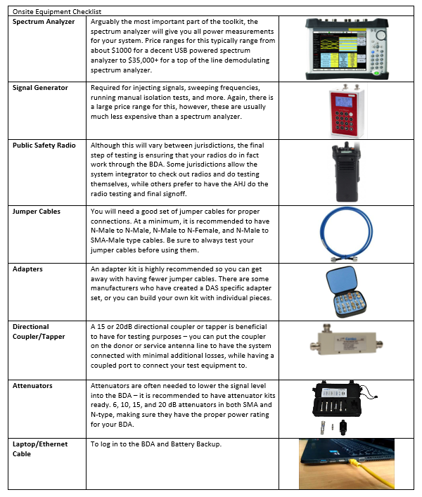
You should not show up to the jobsite missing any of this equipment (except maybe the radio). The commissioning procedure to follow will use all parts from this list. However, sometimes you do need a bit more. The other equipment I keep in my toolkit includes:
- PPE: Depending on the building, I make sure I have all required PPE to enter. PPE includes a hard hat, protective goggles, hard toe workboots, and a safety vest
- Multimeter: For troubleshooting power and alarm issues.
- Multibit Screwdriver: I have all the standard bits and an electronics screwdriver set.
- Crescent Wrench and Adjustable Pliers: I also have a 5/16 wrench for SMA connectors.
- Termination Loads: Just in case.
- Fiber One-Click Cleaner: For when you are working on fiber systems – this is easy to carry around.
PART 2: WHAT TO DO PRIOR TO GOING ON SITE
To make sure you are prepared once you get to the job site, there are some steps to take prior to deployment to ensure you are successful. This includes verifying the link budget, tower locations, system design, and system expectations.
STEP 1: VERIFY DONOR TOWER LOCATION
Verify with the AHJ, communications office, or other person having authority to be able to quickly check that the donor antenna is pointed to the correct tower.
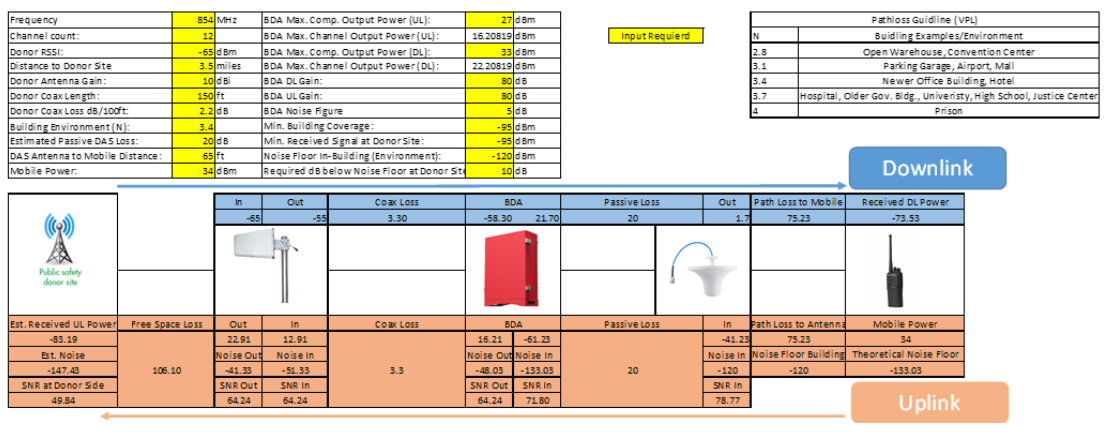
STEP 2: CREATE AN EXPECTED OFF-AIR LINK BUDGET
Save time onsite and create your expected link budget before going to the job site. Figure out the distance to the donor tower, the ERP of the tower, the expected received signal, and the expected BDA input (and use this to compare on site). Calculate expected gain values so you can figure out what your minimum isolation will need to be. If this is all done in Excel, you can enter your measured values once you get onsite and have it immediately tell you the new BDA settings based on your measured values.
STEP 3: STUDY THE DESIGN
Verify that the coverage of the design appears to meet the jurisdiction requirements. Make sure all areas of the building are covered (or if preliminary data shows only partial coverage is necessary, make sure all necessary areas are covered). Know where the head end is, how the cable is run, and where all antennas are. Figure out what your expected DAS signal will be in the head end (this is a quick thing to check once you finally turn the system on, so knowing the expectation can validate your system). Look for and mark any critical areas on the floor plans, so you will know where to check for required coverage areas.
Completing these steps will improve the process of commissioning the BDA and shorten the time spent troubleshooting onsite.
PART 3: VALIDATE THE INSTALL UPON ARRIVING TO THE JOB SITE
If possible, the first thing I do upon arrival to the jobsite is validate the installation. If you can meet with the lead installer to have them show you the system, this is even better because they will have the as-builts and be able to tell you about any changes that were required upon install. These steps don’t need to be done in any particular order, but they should all be completed. From the rooftop down, I typically check the following before ever logging in to the BDA:
- Donor Antenna Installation
o Is the donor antenna securely mounted?
o Is the azimuth correct?
o Is this the antenna that was on the permit set?
o Does it have line of site to the donor tower?
o Is the connector weatherproofed?
o Are the mast and antenna both grounded?
o Was outdoor rated cable used?
o Is there a weatherhead or other waterproof entrance into the building?
- Lightning Protection
o Is there a lightning protector installed?
o Does it pass or block DC, as required per install?
o Is it grounded properly?
- Donor Antenna Cable Run
o Is this cable run in conduit, as required?
o Is this cable run in a rated enclosure, as required? (typically 2-hour for donor cable)
o Is this cable run riser/plenum rated, as required?
o Is there a jumper into the BDA? Note: although this is not required, running a ½” rigid coaxial cable into a BDA makes for a more difficult time disconnecting/reconnecting the cable. I always prefer to have a 3’ flexible jumper at the end to make the connection into the donor terminal on the BDA.
- BDA
o Is the BDA properly mounted?
o Is it in a rated room, as required?
o Is there power to the BDA?
o Has all alarming been connected?
o Is the BDA grounded?
o Is there proper clearance in front of and below the BDA?
o Is there an EPO switch for the BDA, if required?
o Are all accessories still with it? (user manual and keys are the two main accessories typically left behind after install)
- BBU
o Is the BBU properly mounted?
o Have the batteries been installed correctly?
o Is it in a rated room, as required?
o Is there power to the BBU?
o Is the power to the BBU in conduit on a dedicated circuit?
o Has all alarming been connected?
o Is the BBU grounded?
o Is there proper clearance for the BBU?
o Is there an EPO switch for the BBU, if required?
- Service Antennas and Passive Infrastructure
o Are all cables, splitters, and antennas installed in the correct locations?
o Are all cables and splitters in rated enclosures, as required?
o Are all components connected properly?
This is not an exhaustive list of questions, but it will ensure you have inspected the installation as needed. Depending on your jurisdiction, this list can be edited to match the local requirements.
PART 4: COMMISSIONING THE BDA
STEP 1: MEASURE OFF-AIR SIGNAL
Measure the off-air signal at the input to the BDA. Plug your spectrum analyzer into the donor cable input to the BDA and record the control channel signal strength. This should be close to what you expected based on your calculated link budget. Update the numbers from your link budget with this new, actual value. Calculate your actual gain required for full output and the required isolation to achieve this gain.
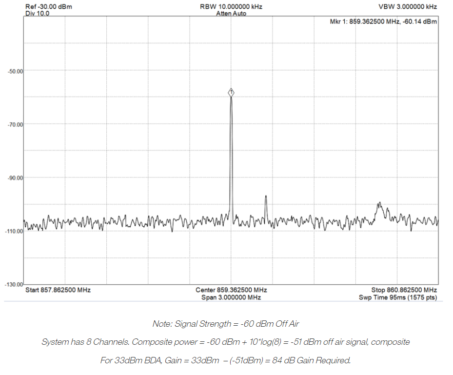
Widen the span on your spectrum analyzer to look at the wideband input to the BDA. Ensure that there are no strong interferers that may affect the downlink ALC. Be wary of adjacent cellular signals – if there is an adjacent cellular signal that is more than 10dB stronger than the public safety signal it could impact the downlink performance of the BDA. In this case, consider cellular rejection filters, such as the Comba FP-78-IN1.
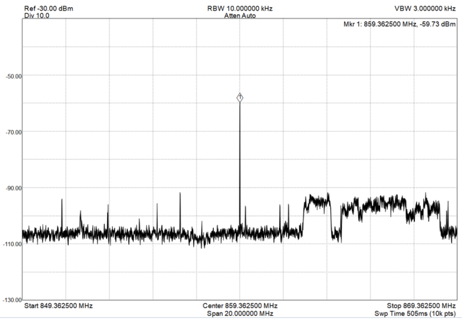
Note the cellular signal on the right side of the screenshot. Our public safety signal is well above the cellular signal strength so we will not need any additional filtering here.
STEP 2: TEST ISOLATION
Although automatic isolation testing is included in all Comba’s BDAs, this walkthrough is going to include manual testing as part of commissioning. This section may be skipped, but no BDA guide is complete without it.
The image below shows the general setup for testing isolation. From the previous step, leave your spectrum analyzer plugged into the donor antenna line. Plug a signal generator into the service antenna line. On your spectrum analyzer, find a clean frequency (a frequency without a noise or signal on it). Set your signal generator to that frequency at the maximum output power (note: do not transmit above 30dBm into the service line – most field signal generators have a max output of 10-20 dBm). Depending on your jurisdiction’s requirements, you may need to measure at certain frequencies or find a low, middle, and high frequency to measure.
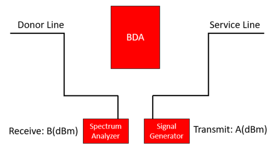
Your total isolation is the transmit power minus the receive power. For example, if you output +20 dBm from your signal generator and measure -95dBm on your spectrum analyzer, the isolation is 20 dBm – (-95 dBm) = 115 dB.
It is good practice to measure isolation while injecting into both the donor line and the service line (to simulate uplink and downlink isolation). When performing these tests, you should use appropriate signals (when injecting into the donor line, use uplink frequencies, and when injecting into the service line, use downlink frequencies). It is important to note that you should not inject a signal into the donor line for an extended period of time or on a frequency that is licensed and being used in the area – this could cause noise on someone’s radio system.
STEP 3: PERFORM SOFTWARE SETUP OF THE BDA
Now it is time to log in to the BDA and set it up.
Log in to the BDA, making sure you are using an incognito or private browsing window. The IP address of Comba BDAs is 192.168.8.101, the username is admin, and the password is admin.
Navigate to the devices page and begin your frequency setup. For a Class A BDA, type in each channel for the system. For a Class B BDA, type in the frequency range for the system. For Class B systems, either enter frequencies based on jurisdiction requirements or find the lowest frequency and round down to the nearest 200 kHz and find the highest frequency and round up to the nearest 200 kHz. For example, if your frequency range is 855.1625 through 857.725 MHz, you would set up the BDA as 855.0 through 857.8 MHz. Turn the RF switches for the channels or sub-bands on, but leave the overall RF switch off.
Go through the BDA commissioning guide and follow the steps. The BDA isolation in the commissioning guide should be close to the isolation you measured previously. When doing the channel setup in the commissioning guide, you should expect to see similar numbers to what was measured with your spectrum analyzer and calculated in the link budget. See the BDA user manual for more information on the BDA commissioning guide.
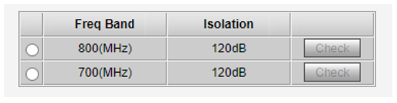
Sample Isolation Test Results – Note: Minimum Isolation for 84 dB of gain is 84+20 = 104dB
Once complete with the commissioning guide, ensure your RF services are all turned on. Set the downlink gain to what was measured with your link budget. Look into the appendix for how to do a proper link budget. At this stage, I recommend leaving the uplink gain set to the lowest setting while doing downlink testing, then coming back to set up uplink once completed.
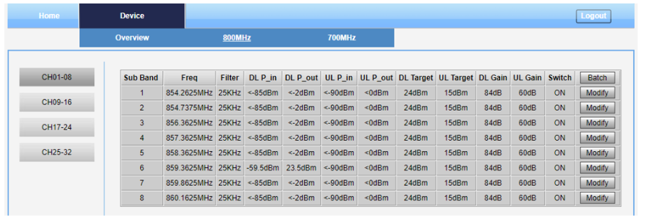
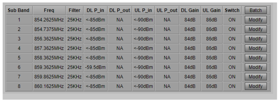
Channel Setup of the BDA
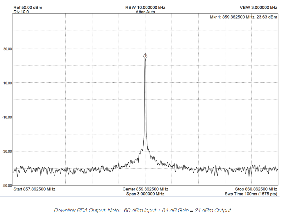
Unplug the service line from the BDA and connect your spectrum analyzer to the MT port on the BDA (make sure you use attenuators as necessary). Check that your downlink output from the BDA is what you would expect based on the input and the gain (note: Output = Input + Gain). This will be your Downlink BDA Output. You can also verify that the wideband downlink output does not have any additional spurious emissions that could affect your system.
STEP 4: ANTENNA VERIFICATION TESTING
We are going to break downlink testing into two categories: antenna verification testing and final grid testing. In between the two, we will be setting the uplink gain.
For antenna verification testing, you will walk underneath each antenna and make over the air measurements of the signal strength of your system at about 5 feet away from each antenna. Verify that the signal strength you are seeing is as expected (your iBwave or Ranplan design should have an expected output from each antenna, and free space path loss at 5 feet of distance is about 35dB for 800MHz and 30dB for 470MHz. If your antenna output is -10 dBm per channel, you would expect to see -45 dBm at 5 feet away on 800MHz or -40 dBm at 5 feet away on 470MHz).
Use this test as a validation of the installation. If one of the measurements is significantly higher or lower than expected, you may have a bad cable or a reversed coupler.
Record the maximum value that you see at 5 feet away from an antenna. This will be your Downlink Maximum Measured Signal.
While doing the antenna validation test, go to the expected worst signal coverage areas as well (this can usually be found by looking at the prediction heat maps or by studying the building and finding the spot furthest away from an antenna or with the most walls between it and an antenna). Record the lowest signal that you measure – this will be your Downlink Minimum Measured Signal.
STEP 5: UPLINK SETTINGS
Unless you have someone at the donor tower measuring the uplink received signal strength, configuring the uplink is going to be based on calculations only. We want these calculations to be as accurate as possible. Below is a sample uplink gain calculation table:
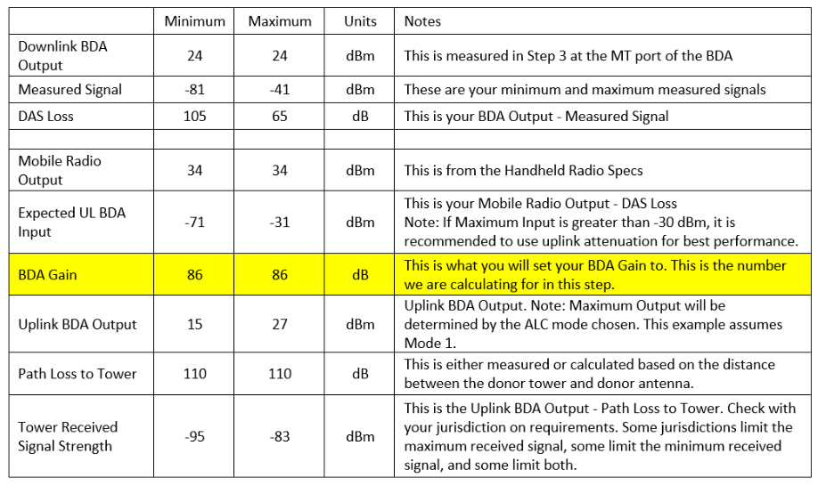
In this table, the Downlink BDA Output was measured at the MT port of the BDA in Step 3 and the Measured Signal are the Downlink Maximum Measured Signal and Downlink Minimum Measured Signal that were measured over the air in Step 4.
DAS Loss is calculated with the equation DAS Loss = Downlink BDA Output – Measured Signal. Note that the minimum measured signal corresponds to the maximum DAS loss, while the maximum measured signal corresponds to the minimum DAS loss.
We start the uplink section with downlink measurements because we assume that the reverse link budget is the same as the forward link budget for passive losses. At this point, I will concede that it is more accurate to have a radio in hand and make actual measurements or use a signal generator set to the same power level as a radio to make the measurements. In practice, most system integrators do not have these tools, so we must work with what we have.
The Mobile Radio Output is the power output from the handheld radio. You can either look up the brand that is used in the jurisdiction, ask the AHJ, or ask the communications department for this information.
The Expected UL BDA Input = Mobile Radio Output – DAS Loss. To ensure the best performance from the BDA, it is recommended that your maximum UL BDA input is not greater than -30dBm. If it is, and your downlink cannot be attenuated, you may use external attenuators inside the BDA to reduce the UL input power only.
Side note: Let us quickly go over design philosophy while talking about the Expected UL BDA Input. When designing a Public Safety DAS, the usual goal is to ensure the system coverage level is greater than -95dBm. In the example above, convenient numbers were used to make this look easy to do. What if, instead of -45 dBm as our maximum measured signal and -85 dBm as our minimum, we had -35 dBm and -95 dBm, respectively. That puts our expected UL BDA input at -21 dBm maximum and -81 dBm minimum. Based on the maximum of -21 dBm, I would want to put a 10dB attenuator on the UL side of the BDA, but based on the -81 dBm minimum, if my gain is set to 90 dB without adding this additional 10dB attenuator, the signal is reaching the donor site at -101 dBm. What can make this situation worse is having two first responders in the building, one at the minimum measured signal location and one at the maximum measured signal location, trying to communicate on different talk groups. Please read about the near-far problem for more information. Although a BDA can help mitigate this issue, the best way to ensure proper functionality of the system is to make sure you have a good design to begin with, that incorporates a sufficient number of antennas.
The BDA Gain is next on the table, but this is usually entered last. This will be the setting we will enter into the web GUI.
The Uplink BDA Output = UL BDA Input + BDA Gain. The minimum is usually simply Minimum Input + Gain, but the maximum is usually ALC limited (which is perfectly fine and a normal function of the BDA). Based on your ALC Setting (Mode 1 is total power shared by number of active channels, Modes 2 and 3 are total power shared by number of programmed channels), the Maximum UL BDA Output is either going to be based on the spec sheet maximum output, the spec sheet maximum output split equally between the number of channels, or for rare cases, the maximum UL BDA Output will just be the UL BDA Input + BDA Gain.
The Path Loss to Tower can either be calculated using the distance to the tower and transmission line losses, or if the ERP of the downlink signal at the tower is known, can be calculated by Path Loss to Tower = Tower ERP Output – Downlink BDA Input.
Check with your jurisdiction on requirements for the Tower Received Signal Strength. This is calculated with the formula Tower Received Signal Strength = Uplink BDA Output – Path Loss to Tower. It is recommended that you enter the jurisdictional requirements here, then find out what gain is needed at the BDA to achieve these requirements.
Once calculated, we can now program the UL gain setting into the BDA.
BDA Settings after setting UL Gain.
Note: The UL noise floor has been ignored for these calculations so far. Look for a future update that expands on how to calculate the thermal noise floor at the donor tower.
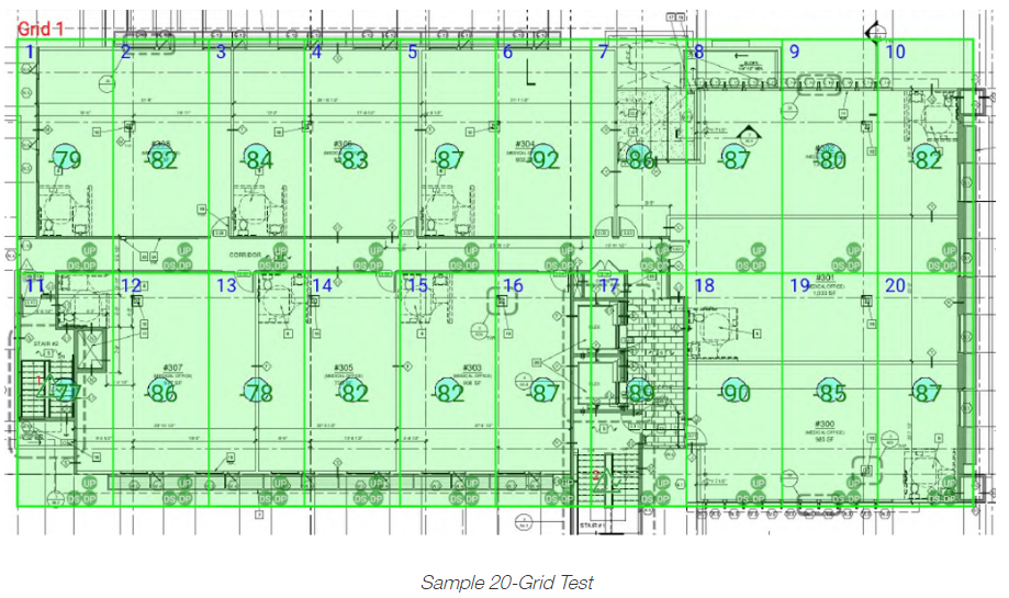
STEP 6: FINAL GRID TESTING
Now that we have both UL and DL set as needed, we can do the final grid testing. Split your floors into 20 grids (or the appropriate amount as required by your jurisdiction) and make signal level measurements in each grid. If you have a radio, perform a DAQ test in each grid. Otherwise, walk with the AHJ to ensure their radio works in all places they deem appropriate to test (again, this will vary greatly by jurisdiction).
Once everything passes, it is recommended to go back to the BDA and export the BDA RF settings and include this in your grid testing report. This will make it easy to validate settings during future annual inspections.