Virtually every in-building system that reradiates an off-air signal is subject to the detrimental effects of isolation on system performance. Poor isolation can result in lower gain. Lower gain can result in less output power available for meeting coverage requirements.
My June 28th, 2018 Tech Brief, which can be found under the “Tech Briefs” section of Comba’s home page, or by clicking here, explains in detail the relation between gain and isolation. I would encourage our readers to review the “Gain vs. Isolation” article as it builds a good foundation for understanding this articles topic of “Isolation Resolution”.
Isolation Definition
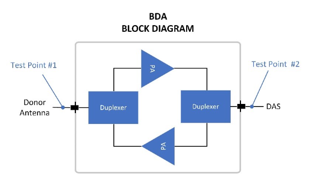
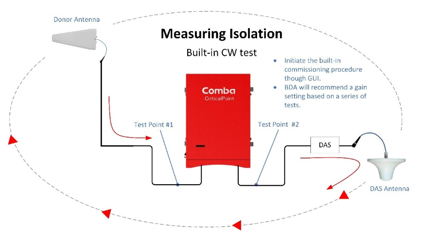
Isolation, as it relates to Public Safety Emergency Responder Radio Communications Systems (ERRCS), is defined as the amount of signal attenuation measured between two points in the system. Typically, these two points are the duplexed ports on the BDA. Refer to test points 1 & 2 in diagram below. Isolation is bi-directional, meaning it is applicable to both the uplink and downlink paths.
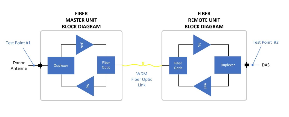
In a fiber-based system, the two points we are referring to are the input to the headend Master Unit and the output from the fiber remote unit in the downlink path, and input to fiber remote and output from Master Unit in the uplink path.
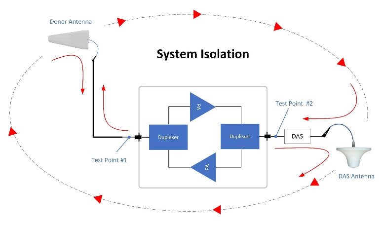
Looking at it from a system perspective, isolation refers to all RF attenuation losses between test points 1 & 2 to include passive DAS losses from cables, splitters, antennas, and other factors affecting RF as it propagates over the air such as building density and distance.
Why is Isolation a concern?
As pointed out in the “Gain vs. Isolation” Tech Brief, a BDA device amplifies RF and reradiates the same signal that it receives. To keep the BDA from receiving and boosting its own signal, sufficient isolation must exist to prevent a destructive feedback loop. This feedback process is commonly referred to as oscillation. Oscillation can drive the BDA into saturation, which in turn results in increased levels of noise interference and the generation of harmful intermod products.
National Codes such and NFPA 1221 (2016) and IFC 2018 require that isolation is maintained at 20dB greater than system gain. What this means is that if, for example, your in-building design requires 90dB of gain, then the system isolation between Test point 1 and 2 must be 110dB minimum.
Code also requires oscillation prevention circuitry, so again, why is isolation a concern?
True, many BDAs do have oscillation prevention circuity built-in, however, this circuitry functions by limiting output levels through gain reduction. Lowering gain will most likely have an adverse effect on system performance. Lack of gain caused by low isolation is one of the most common symptoms of poor coverage.
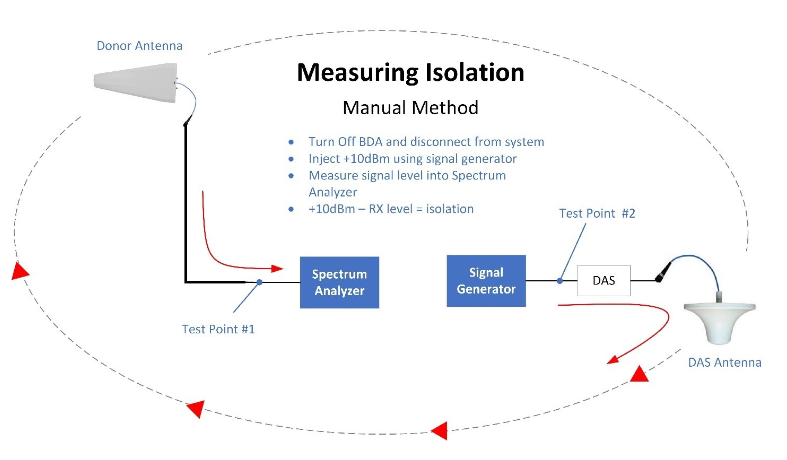
Measuring Isolation – Manual Method
Measuring isolation is an easy process that requires a signal generator and spectrum analyzer. Simply remove the BDA from the circuit and replace with signal generator and spectrum analyzer as depicted below. Set signal generator to a known idle frequency preferably within the operational band and at a level between +10dBm and +30dBm. Inject this signal into DAS via Test Point #2. Tune spectrum analyzer to signal generator’s frequency and measure signal at Point #1. The signal level delta between TP#1 and TP#2 represents the isolation.
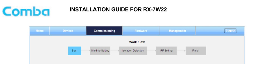
Measuring Isolation – Using Built-in CW generator
I can’t speak for other manufacturers in the industry, but Comba has a very popular feature for measuring isolation. Comba’s Public Safety BDAs and Fiber Based systems have an easy to use web-based GUI that includes a commissioning process. This commissioning process guides the user through a work flow that uses a built-in Continuous Wave (CW) signal generator to determine system isolation without removing cables or powering down BDA. Comba’s built-in signal generator & RF signal measurement circuitry eliminates the need for lugging around heavy test equipment, or at least as it relates to isolation testing.
The following diagram illustrates the configuration for measuring isolation using Comba’s built-in isolation test feature. This method has proven to be every bit as accurate as the manual test method. AHJs are beginning to use this built-in isolation measurement feature as an acceptable step to proving compliance with the “isolation can be no less than 20dB greater than system gain” code requirement.
What causes low isolation?
Radio Frequency waves and how they react to various construction materials within a building or even with nearby buildings is difficult if not impossible to explain. Some materials will absorb RF signals and other will reflect it. Other factors that challenge our ability to model RF coverage in-building are phenomena such as refraction, multipath, and ducting.
The most common cause of low isolation is from an indoor antenna placed in close proximity to the donor antenna, which may lead to lower than expect isolation.
In some rare cases, one may find that a ceiling antenna 3 levels below the donor antenna has lower isolation than an antenna only one floor down from the donor antenna. This could be caused by a ducting effect, whereby some RF may be leaking into pipes or duct work. If the ventilation system dimensions are an optimum wavelength for a particular frequency, then the duct may act similar to a waveguide allowing RF to propagate through with very little attenuation.
As mentioned in the “Gain vs Isolation” Tech Brief, poor isolation, or a change in isolation, can be a result of shipping dock doors being opened, a building shape where indoor antenna is line-of-sight to donor antenna, or using a low gain donor antenna. Low gain antennas generally have wide vertical beam-widths and may offer gain to indoor paths.
Don’t forget to check the value of your directional couplers and their orientation. I say this because during a recent support call, I learned that the installer reversed the pattern of directional couplers from what was called for in the iBwave design plan, which resulted in the lowest coupling ratio being closest to the BDA, and the BDA was installed at the top floor nearest to the Donor antenna. This oversight resulted in about 20dB higher power routed to the top floor. Once corrected, isolation increased by 20dB, which meant gain increased by 20dB and consequently we were able to achieve our targeted output power and comply with coverage requirements.
Localizing the cause
If your isolation measurement minus 20dB equals a gain value lower than expected, lower than your system can tolerate, following these steps to zero in on the cause:
- Confirm directional coupler and splitter placements and orientations match your design.
- Inspect integrity of connectors and jumpers around the BDA to make sure no RF energy might be leaking out.
- Turn off BDA Power Amp–usually a software setting—and using a 50 Ohm load, terminate the directional coupler/splitter port that feeds the top floor, or whichever floor is nearest to the donor antenna. If your design has multiple riser/feeds, then terminate all applicable branches on a given floor. If isolation improves, then systematically isolate down to a specific antenna and either change directional coupler ratio or add attenuation as necessary.
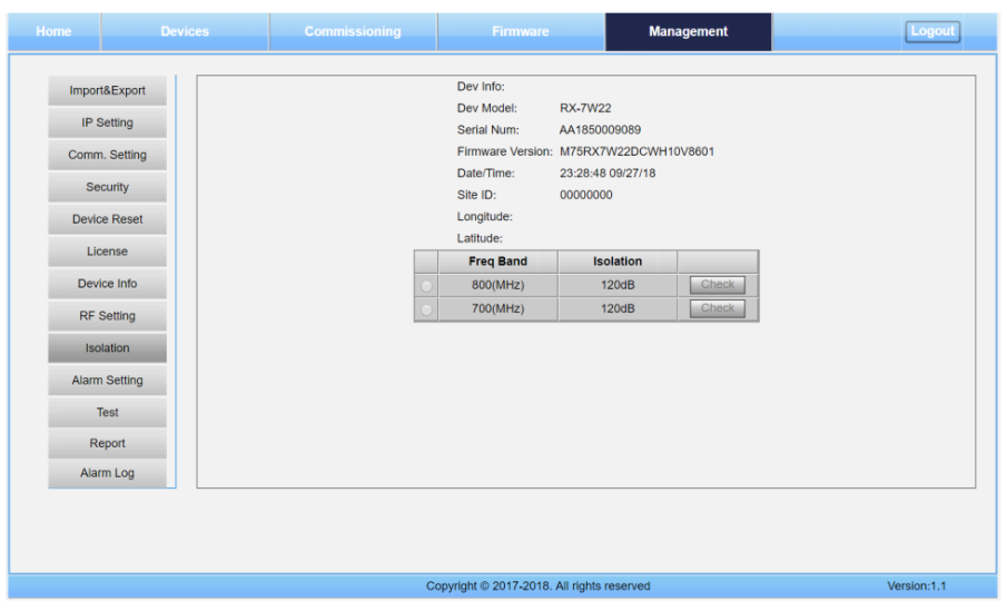
*Note: If using Comba product, after terminating floors or branches of the DAS, go to the “Management” tab in the GUI, click “Isolation” bottom left side of screen. Select which band you would like to run isolation test on and click “Check” button to start test.
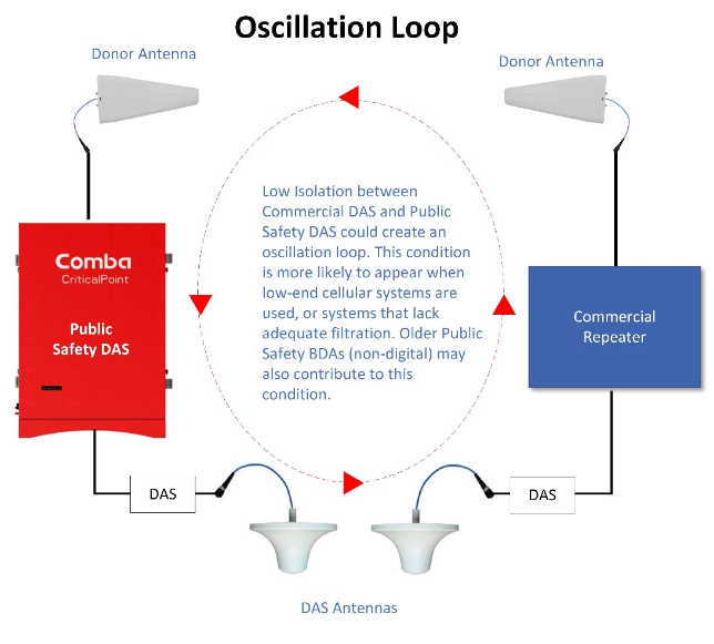
4. If isolation does not change after completing previous steps, consider the possibility of interference from a commercial DAS. If, for example, a cellular DAS exists in the same building and the downlink Public Safety signal, say at 851MHz is getting into the commercial DAS uplink path and being reradiated from the cellular Donor antenna, then it is quite possible the two systems will form a feedback loop.
Completing the previous steps should have a marked improvement on Isolation, however, if still not enough, then consider replacing the donor antenna with a higher gain, more directional one. A high-gain, narrow beam-width donor antenna has the following benefits:
- Stronger signal into the BDA, which means less gain needed to achieve max power out.
- If BDA gain can be lowered, then isolation requirement can also be lowered.
- Higher gain donor antennas typically have narrower vertical beam widths, meaning less signal will bleed into building from main/side lobes.
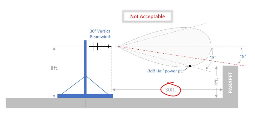
A Note on Donor Antenna Mounting.
It is standard practice to spec an antenna by it’s half power beam width, or 3dB down point. If an antenna has a 30-degree beam width, then 15 degree either side of the main lobe is the half-power (-3dB) point. The general rule for antenna mounting is to mount such that nothing obstructs the RF path within this 3dB half power beam width. I often see non-penetrating antenna mounting systems on rooftops with masts that violate this rule. In the following example the Antenna is mounted on an 8ft. mast 30 feet back from a 4ft. high parapet. In this example the parapet partially obstruct the main lobe of the antenna.
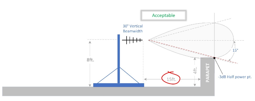
In this next example, the antenna mounting system has been moved to within 15 feet of the parapet where it can no longer distort or degrade the antenna performance.
Takeaways
A common scenario: Your in-building RF modeling tool shows great coverage using the 2W, 90dB gain BDA. And you measured your off-air signal level, so you know that the BDA has enough gain to hit the desired output power. What you couldn’t predict was the amount of isolation your installation would dictate. Now you’re under the gun and stuck trying to remedy a problem that is tough to anticipate.
The good news is that it is relatively easy to track down which floor and even which antenna might be causing the low isolation problem.
Remember, the weaker the off-air signal, the more gain that will be required. The higher the gain, the greater the likelihood you’ll experience isolation issues. If you know your off-air signal will be weak, bite the bullet and buy the $800 donor antenna up front.
Check your Installation. Using the wrong coupling ratios in the wrong places can cause grief.
Follow best practices when installing the donor antenna. Do not obstruct the main lobe, nor the antenna’s ability to properly form the beam. A little attention to the donor antenna can have a major effect on improving isolation.
Be cautious of cellular systems within the same building that use off-air repeaters as signal source and that do not have adequate filtering to stop out-of-band signals. They may be contributing to your isolation issues.
And be ready to demonstrate to your AHJ that system isolation is indeed 20dB higher than BDA gain. Our national codes require it, and many AHJs are requesting proof of it.