“Radio Test 1, 2, 3…”
This is a common phrase we hear as the AHJ walks through the building during acceptance testing. A lesser common phrase we are now starting to hear is, “Okay, let’s perform near-far testing.” While near-far itself isn’t new, the code and implementation of said code are, and will affect future DAS designs. As such, this is a topic all integrators need to understand.
Near-far occurs when two radios of equal power key up at the same time, but at different distances from the service antenna. In the case of a BDA DAS solution, this would be represented as the delta in the loss between the strongest and weakest signals under an antenna. The strongest signal would be directly under an antenna (but not greater than 10 feet) and the weakest is X dB loss from the antenna before the next nearest antenna starts to improve the radio signal strength. X dB is the combination of path loss and any additional attenuation like walls or pillars. Please see Figure 1 below for reference.
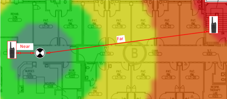
Figure 1.
Uplink (Power/Channel) | |||||||
Input (dBm) | BDA Set Gain (dB) | BDA UL Target Output (dBm) | Output (dBm) | Line Loss (dB) | Donor Gain (dBd) | Free Space Pathloss (dB) | Received Signal at Donor Site (dBm) |
-45 | 85 | 27 | 27 | 3 | 10 | 107 | -73 |
-85 | 27 | 0 | -100 | ||||
Table 1
The AHJ has stipulated that the maximum input at the donor tower will be no greater that -75dBm, but the above link budget calculation has a peak signal of -73dBm, which will result in a “failure”. To correct this discrepancy, you be required to add 2dB of physical or software attenuation to the UL output of the BDA and increase the BDA gain by 2dB (87dB). This net-zeros your weakest signal and lowers your strongest signal to -75dBm, now passing your AHJ’s requirements. As shown in Table 2 below.
Uplink (Power/Channel) | ||||||||
Input (dBm) | BDA Set Gain (dB) | BDA UL Target Output (dBm) | Output (dBm) |
Atten (dB) | Line Loss (dB) | Donor Gain (dBd) | Free Space Pathloss (dB) | Received Signal at Donor Site (dBm) |
-45 | 87 | 27 | 27 | 2 | 3 | 10 | 107 | -75 |
-85 | 27 | 2 | -100 | |||||
Table 2
Two Radios:
When both radios key up at the same time, and with the BDA gain now set to 87dB, the BDA will use the internal ALC/AGC functions to “limit” the BDA gain with respect to the BDA maximum composite output power of 27dBm (BDA spec sheet), thus not overdriving the internal amplifiers, BUT this automatic gain reduction will cause the second radio signal not to reach the tower at minimum AHJ specification of -100 dBm, as it is now -115dBm. As shown in Table 3 below.
Uplink (Power/Channel) | |||||||||
Input (dBm) | BDA Set Gain (dB) |
AGC/ALC (dB) | BDA UL Target Output (dBm) | Output (dBm) |
Atten (dB) | Line Loss (dB) | Donor Gain (dBd) | Free Space Pathloss (dB) | Received Signal at Donor Site (dBm) |
-45 | 87 | 72 | 27 | 27 | 2 | 3 | 10 | 107 | -75 |
-85 | 27 | -13 | -115 | ||||||
Table 3
To resolve this issue, we have two options: 1) Add antenna density and/or, 2) change the BDA to a Class A (channelized) device. Adding antenna density will allow you to balance out the power of the system into the BDA and require less balancing of hard attenuation and software gain. Changing to a channelized Class A BDA has the added benefit of balancing power on a per channel basis. Each channel will receive its total allotted power without other channels affecting it when they are also keyed up.
Using our scenario above with a Class A BDA and only two channels, each channel will have 24dBm of allotted output. The difference this time is that each channel’s gain has independent AGC and do not affect each other.
The below link budget example shows how the BDA automatically sets individual channel gains using the two radio frequencies. As shown in Table 4 below.
Uplink (Power/Channel) | ||||||||
Input (dBm) |
BDA Set Gain (dB) | AGC/ALC (dB) | BDA UL Target Output (dBm) | BDA Output (dBm) | Line Loss (dB) | Donor Gain (dB) | Pathloss (dB) | Received Signal at Donor Site (dBm) |
-45 | 90 | 69 | 24 | 24 | 3 | 10 | 107 | -76 |
-85 | 90 | 90 | 24 | 5 | -95 | |||
Table 4
The “BDA Set Gain” is 90dB on the UL. The “AGC/ALC” tailors the individual channel gain(s) based on the UL Target Output setting. The total output power per channel is represented in the “BDA Output”. This will now pass donor tower requirements and DAQ won’t be affected, but this scenario only works if these are two separate frequencies.
NOTE – P25-phase II Specs (Where one frequency can support two TDMA voice channels/two radios): Based on the above scenario, and this is rarely seen in the field, if the two radios are assigned to the same frequency, the BDA individual channel gain would be used for both radios, and you would be left with the same result as using a Class B BDA. The best way to fix this problem would be option 1; increase antenna density or deploying a BDA that utilizes AGC per time slot.
The below link budget example will look at a more realistic scenario of using a Class A BDA with 12 channels and a maximum gain setting of 85dB to clean up the noise floor by 5dB. As shown in Table 5 below.
Uplink (Power/Channel) | |||||||||
Input (dBm) | BDA Set Gain (dB) |
AGC/ALC (dB) | BDA Target UL Output (dBm) | Software Attenuation (dB) | BDA Output (dBm) | Line Loss (dB) | Donor Gain (dB) | Pathloss (dB) | Received Signal at Donor Site (dBm) |
-45 | 85 | 61.2 | 16.2 | 0 | 16.2 | 3 | 10 | 107 | -83.8 |
-85 | 85 | 85 | 16.2 | 0 | -100 | ||||
Table 5
The above link budget shows that the DAS solution is still within the AHJ min/max tower receive specifications, but the 40dB delta between the two inputs into the BDA (MT port) will need to be decreased. Some AHJ’s require a delta of not more than 25dB to minimize the near-far affect issues. To decrease the 40dB delta, the solution is to increase antenna density which will balance out the signal before it reaches the BDA.
Had the original design included a higher antenna density from the beginning, time, energy, and cost for post balancing the DAS and changing from a Class B to Class A BDA would have been avoided. This brings us back full circle of IFC code 510.4.2.8: “Radio communication antenna density. Systems shall be engineered to minimize the near-far effect. Radio enhancement system designs shall include sufficient antenna density to address reduced gain conditions.”
While more antenna density vs BDA classification cost varies on a per project basis, the effects of near-far on the overall design are absolute and the link budget must be taken into consideration.
Tower distance, antenna density, donor antenna gain, channel count, can all affect which BDA classification is best to use. The below excerpt is from a previous Tech Brief Comba has published on Class A vs Class B systems to help understand how those variables can come into play.
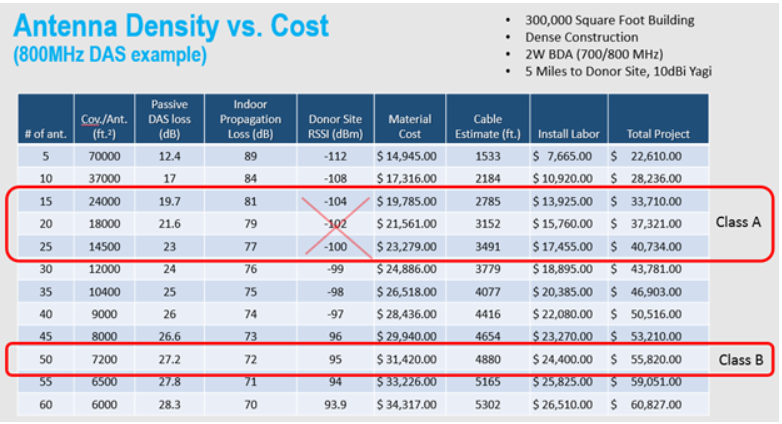
“The higher density of antennas needed to comply with code in Class B applications can have a serious impact on your budget. The following table shows how using a Class A device for a 300,000 square foot building has a “sweet-spot” range of between 15 and 25 antennas. I have crossed out the “Donor Site RSSI (dBm)” portion of the Class A range because these levels are only applicable to Class B uplink calculations where reduced gain from the near condition limits the gain available for the far condition. Recall that the Class A devices have independent gain per channel and as such will generally have at least 30dB more gain available in the uplink path than a Class B device with gain being compressed by the near condition. Now let’s look at the values in the Class B scenario which requires 50 antennas to meet the -95dBm target value back at the donor site receive equipment. With the doubling of antennas and couplers combined with additional cable and installation costs, any savings by choosing Class B over Class A is gone.”

You can read the complete discussion at https://combausa.com/en/tech-briefs/class-a-vs-class-b.
In summary, solving the near-far problem issue can be done by increasing antenna density or utilizing Class A technology. For the very small incremental increase in overall cost, doing both provides a means of truly fine tuning the system design (even after installation) to ensure that the near-far problem is eliminated. Another benefit of higher antenna density, is it allows lower BDA gain to be set which also decreases the BDA output noise.