Fiber the Right Way
Fiber, the core infrastructure of any long-distance communication for modern technology. As such, if there are any problems with this core, or backbone, these problems are amplified at the end devices trying to communicate with each other.
Single Mode (SM) VS Multi Mode (MM):
There are two types of fiber mediums currently available, Multimode (commonly referred to as MM and designated with a light blue or orange color sheath) and Single Mode (commonly referred to as SM and designated with a yellow color sheath).
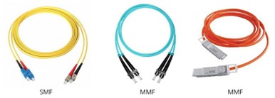
MM fiber is a type of optical fiber designed to carry multiple light rays or modes simultaneously. The key characteristic of MM fiber is the core thickness of each fiber strand is approximately 5X that of SM fiber. This allows terminating connectors to be made easier and multiple modes of light to pass through each strand. However, that doesn’t come without some costs such as limited bandwidth capacity and shorter distances. Light inside the fiber must bounce multiple times to achieve multiple light modes so they don’t interfere with each other. In turn, you will have an increase in power loss and reduced bandwidth to keep a constant transmission speed.
SM fiber consists of a single glass fiber strand used to transmit a single mode of light (ray). It has a smaller core and only one light mode to focus transmission, thus allowing for a larger bandwidth and can transverse over a longer distance. Think of it like the aperture of your eyes and seeing in daylight vs. at night. During the day, the pupal restricts the aperture to limit the light from 1 source millions of miles away, the sun. But you’re able to see “clear as day”. A lot of information was able to reach the brain for processing. At night, the pupal expands and allows for as much light as possible from as many sources as possible to see since the one focal source of the sun is gone. Additionally, each of those individual light sources are much weaker and the illuminated objects are much harder to see unless you are close. SM fiber does have an additional benefit over MM fiber. The material used to manufacture SM fiber is less expensive. Unfortunately, this is generally outweighed by the cost of the internal components used for receiving and transmitting the optical signals, as SM components are much more expensive to produce due to the higher bandwidth capacity that needs to be supported. Comba only uses SM fiber because of the higher bandwidth capacity as well as being able to transmit over 100m, a limitation of MM fiber.
Connector Body Types:
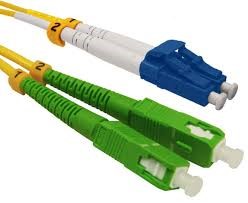
After the fiber cable has been selected, it’s time to decide on the correct connector style. There are several styles to choose from, the two most frequently used in fiber plant installations are the LC and SC body styles and generally do not matter which is selected. The LC connector is small in form factor (1.25mm ferrule), and is typically used in tight fitting situations where space and connector count matters. The SC connector is larger in form factor (2.5mm ferrule) and uses a push-pull clip to stay seated for easy install and removal.
Connector Optical Coupling:
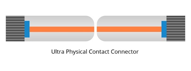
There are two primary optical coupling methods, Ultra Physical Contact (UPC) and Angled Physical Contact (APC). Either coupling methods can be used with LC or SC body style connectors. For Example: LC-UPC, LC-APC, SC-UPC, and SC-APC.
Connector Specifications:
The most important difference to be aware of is the back reflection pass/fail requirements. The LC connector has a higher minimum standard of 5dB greater than the SC connector.
LC Connector |
| SC Connector |
LC/UPC = -55dB |
| SC/UPC = -50dB |
LC/APC = -65dB |
| SC/APC = -60dB |
It is worth noting that a typical connector for LC and SC pass 5 dB greater than minimum requirements if no issues are present. Both types are industry acceptable standards, although it is generally up to integrators to decide on the connector requirement based on the manufacture equipment specifications.
OEM equipment specifications should be double checked and verified for all fiber requirements. For example, Comba uses SC/APC connectors on all their analog fiber equipment, with a fiber loss specification no higher than 8dBo (Public Safety) and a reflectance value no greater than -60dB.
APC and UPC optical couplings are NOT interchangeable. UPC has a slight concave angle to create a focal point for light. This is more noticeable on its sides where the angle is much sharper. The optical return loss of UPC connectors is -50dB or higher.
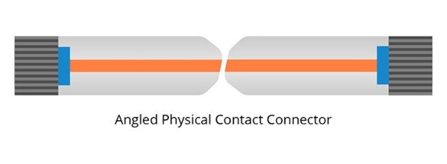
To pursue lower back reflection, the APC fiber connectors were developed. APC refers to Angled Physical Contact, the ferrule endface radius is polished at an 8°angel, thus minimizing back reflections. Due to the angled endface, the reflected light will leak out into the cladding instead of staying in the fiber core. The optical return loss of APC connectors is -60dB or higher.
Since some applications are more sensitive to return loss than others, APC connectors are preferred in these situations, for instance, in higher wavelength range like those used for RF signals, passive optical networks and other WDM systems using single mode fiber.
Pros, Cons, and Examples:
Each connector style and optical coupling will have pros and cons based on specific use scenarios. For example, computer network data connections commonly use UPC connectors. This is because the data between the computers consists of a digital protocol language with error checking features. Since UPC connectors have a reflectance requirement of -50dB, this allows the data network to have more tolerance and is often overlooked during ODTR testing by the integrators. As the digital information passes through a logic chipset, a series of Boolean gates, interprets the signals as 1 or 0 and are absolute. If a 1 or 0 is missing, the gates can use the surrounding 1s and 0s to determine the most logical number missing and interpret the overall command. If it cannot determine the value, it will return an error or skip the value completely, if possible.
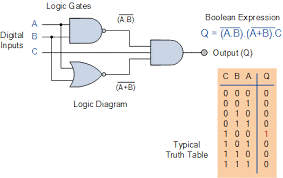
Boolean Logic Circuit
Analog data signals do not operate on 1s and 0s and is considered variable. Therefore, the analog signals must be interpreted based on a preset range of values. The manufacture of analog data equipment will develop the range value limits, and when these signals are outside the limits, data will be interpreted as noise and rejected. Unfortunately, this also leaves room for errors within the range limits, as noise or corrupted values, could be interpreted as correct and cause anomalies with the equipment.
For example, think of this in terms of a MP3 player versus a vinyl record player. The MP3 data is more compact, and it will either, A) play the song due to no data loss, or B) skip sections of the song if data is missing or corrupt. Whereas a vinyl record has a very specific set of characteristics that the record player cannot determine if, A) the record is scratched, B) a flaw with the recording, or C) purposefully recorded into the song. The record player will play whatever it reads, intended or not, and the person listening to the song will hear the defect and will need to mentally process it as part of the original song or reject it. An additional take away from this example is even though the listener mentally rejected the sound, the sound was still played and heard. However, lighter scratches or flaws aren’t as noticeable or even recognized, thus interpreting as how the song was recorded. In essence, the listener is “accepting” those flaws as correct values, and even if incorrect, because the values are within an acceptable range. This is the reason why the record must be clear of any defects and has a higher standard to keep the integrity of the originally recorded song.
The above example translates as to why analog data signals require the APC connector and the higher specifications. APC connectors require a minimum standard of no greater than -60dB reflective loss, which is 20% greater than UPC connectors. Any less, and the first physical communication layer would create distortion onto the second layer of communication, ultimately causing the end-to-end devices to improperly interpret data packets. APC connectors achieve this higher standard because of the 8° fiber coupling angle. Because of UPC’s concave design, the light has a smaller focal point and is pointed directly at the center of the fiber line, thus resulting in higher reflectance values. APC connectors are angled into each other, so the reflectance of the laser is pointed into the cladding of the fiber line instead of the core. Higher tolerances by proxy create better transmission rates than UPC. In a large server, UPC has the advantage because most devices communicate digitally. Therefore, there isn’t as much pressure on optical tolerances of the fiber link between devices. As with anything that has lower tolerances, there is a lower cost involved with UPC than APC, highlighting the UPC’s true advantage over APC. A quick way to identify if an optical coupling/connector is APC or UPC is by the color of the connector itself. APC are GREEN housings and UPC are BLUE housings.
Mechanical and Fusion Splices:
Once the fiber backbone has been installed, and the connectors are purchased, it is time to splice. But should you use mechanical or fusion splicing? Mechanical splicing has the benefit of having a lower upfront tool cost to start splicing, but that’s about where the benefits of mechanical splicing end. Since mechanical splices need to hold cables together, the cost of a mechanical splice connector is much higher than a fusion splice connector. A fusion splice aligns and physically melds two fiber ends together. The jacket of the fusion splice is more or less a heat shrink shielding, thus bringing the per connection cost down significantly. Due to the mechanical connector only aligning the fiber cores together, the insertion loss is also higher, 0.2 dB – 0.75 dB. A fusion splice is < 0.1 dB. While short or digital applications may be able to use a mechanical splice, a fusion splice overall benefits generally outweighs the small niche cases a mechanical splice might be able to use. It is Comba’s recommendation that fusion splices are used to meet equipment specifications.
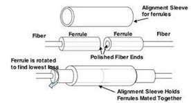
Mechanical Splice
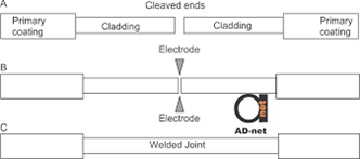
Fusion Splice
Fiber Testing:
The final step is to test the fiber plant end-to-end. This includes all the fiber being used between the RF equipment, including the fiber jumpers making the last physical connection to the equipment. Using an Optical Time Domain Reflectometer (OTDR) tester is the standard for testing return loss and reflective loss. But before testing the fiber, all connectors should be cleaned with either a one-click pen or fiber cleaning cloth. It should never be assumed connectors are clean coming out of the box/bag whether a bulkhead, fusion splice connector, new jumper, or even the RF equipment connector. Small particles can easily get under the cap covers in shipping and especially on construction sites. After the connectors have been cleaned, it’s time to test the fiber with the OTDR. When testing with the OTDR, the RF equipment specification sheet will state what wavelengths to test. Most analog fiber communication systems are using wavelength division multiplexing (WDM) and consists of two optical wavelengths, 1310nm for downlink path and 1550nm for uplink path. These wavelengths are occurring simultaneously and used to transport the RF paths including equipment instructions/alarms/etc. Test results of the OTDR will include insertion loss for each connector, overall return loss, and the reflective loss. The data is represented using a graph of loss over length of the cable and a table explaining what it found at each connector throughout the fiber run.

Cleaning the Bulkhead of a Patch Panel
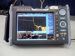
OTDR Tester
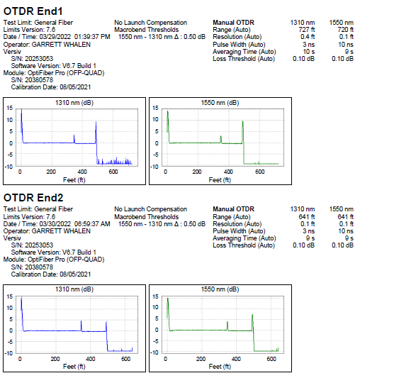
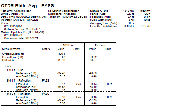
Passing OTDR Testing Result with SC/APC Connectors
Conclusion:
Understanding how the fiber plant functions will save time and headaches while commissioning an RF fiber DAS solution. A good fiber link between devices starts with good fiber prep and ending with certified testing. If any of the above steps are missed or overlooked, an engineer may potentially be troubleshooting RF systems that would otherwise be trouble free. End-to-end fiber testing and doublechecking the results will verify all steps above were followed properly and ensure fiber backhaul data integrity.