Introduction:
The Comba V3 Class A BDA provides new and enhanced commissioning tools within the user interface to assist individuals in DAS commissioning. The new features consist of broadband isolation testing, downlink input testing and a new uplink input test.
Although these enhanced tools will help commission the V3 Class A BDA, the individaul performing the commissioning role should always perform manual testing and compare the collected data with the software results!
There are three methods that can be used:
A: Manual commissioning procedures based on individual test results and link budget
B: Utilizing the internal Comba V3 BDA commissioning tools
C: Combination of the internal Comba V3 BDA commissioning tools and manual commissioning results
Comba recommends option C, as this will provide the best results.
The Comba V3 Class A BDA does not provide a Step-by-Step procedure, but by understanding the below eight general steps, it will assist in the BDA commission process.
1. Enter general device information
2. Enter donor site information
3. Enter channel information
4. Perform isolation detection (NOTE: The BDA will limit gain settings based on isolation test results)
5. Perform downlink input test
6. Perform uplink input test
7. Review recommendations
8. Program the BDA and turn-on
Steps:
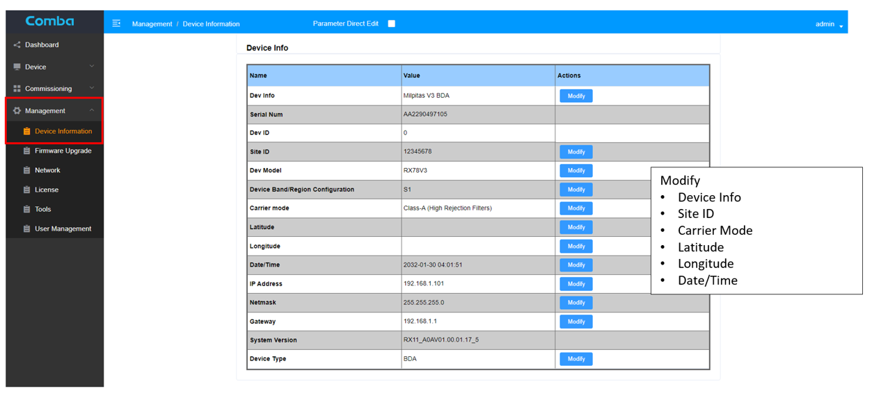
1. Adding General Device Information
Under the Management/Device Information tab, enter the device information using
the Modify Buttons
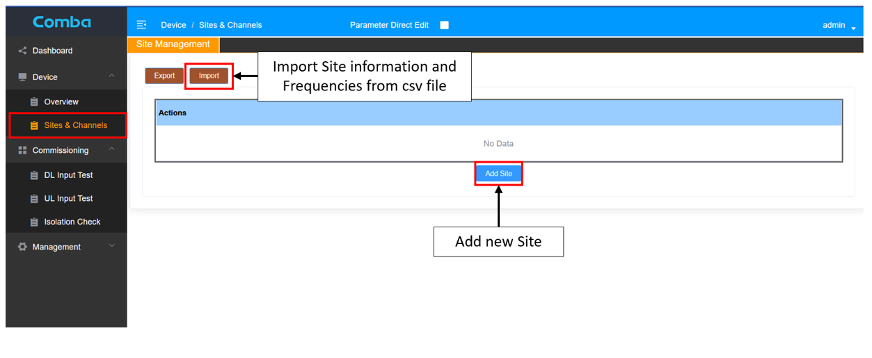
2. Site Management
It is possible to enter the donor site information by selecting import and loading the information from a CSV file from a previously commissioned V3 BDA or enter the donor site information manually by selecting the Add Site button.
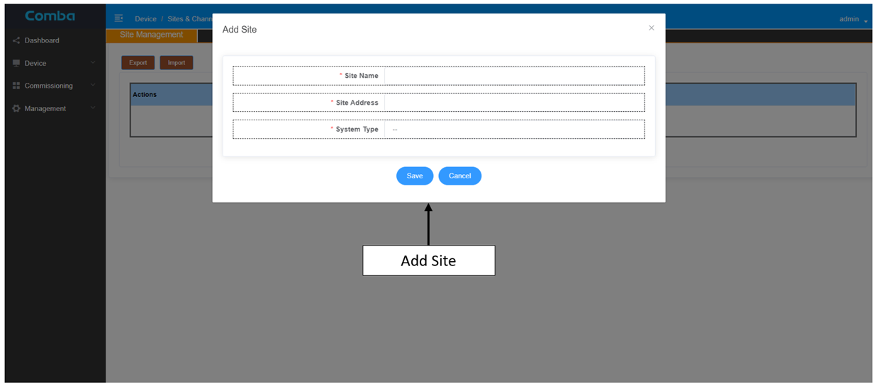
When creating a completely new site, one will have to add the site name, address and system type and click save.
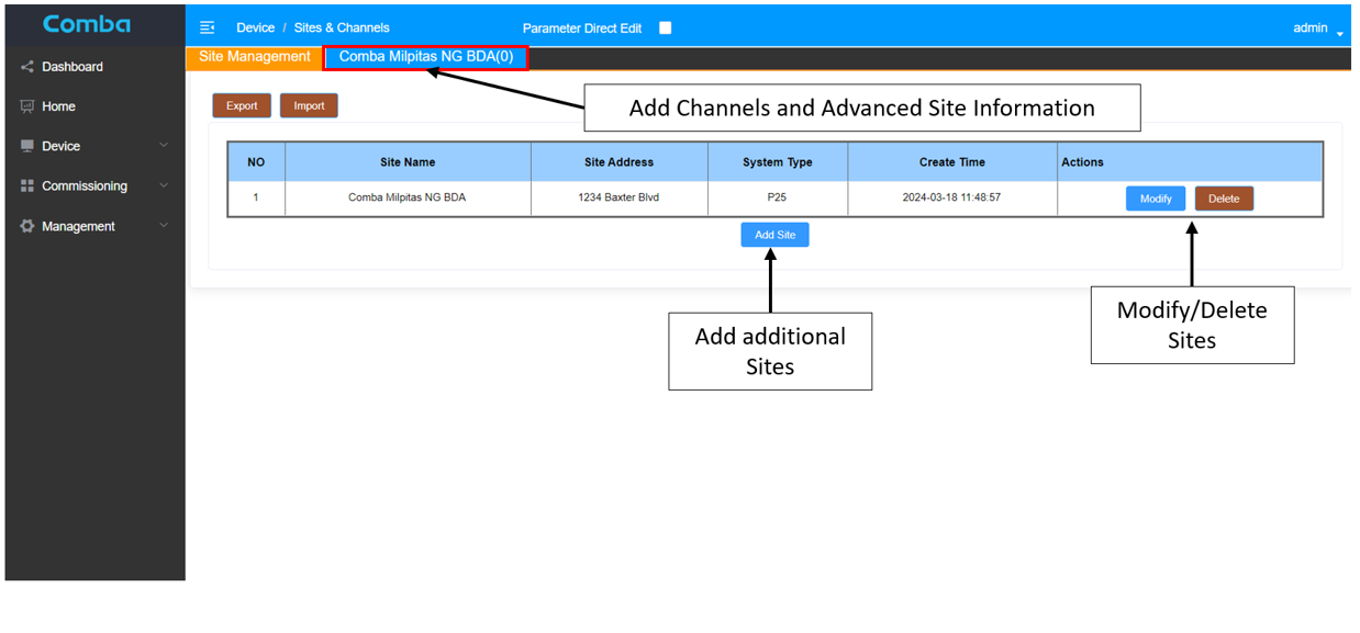
3. Site Information
After creating the site, you have the option to add additional donor sites or use the Modify or Delete buttons to edit or delete existing donor site information.
To add channel information, click on the button located next to the Site Management button
To generate accurate recommendations from the BDA for the commissioning settings, Donor Site Parameters (Donor Site TX ERP, Donor Site TX/RX Delta, Donor Site RX Max RSSI, Donor Site RX Min RSSI) and Site Parameters (BDA Donor Antenna Gain, BDA Donor Cable Loss, BDA Distance to Donor) will have to be filled out by the user.
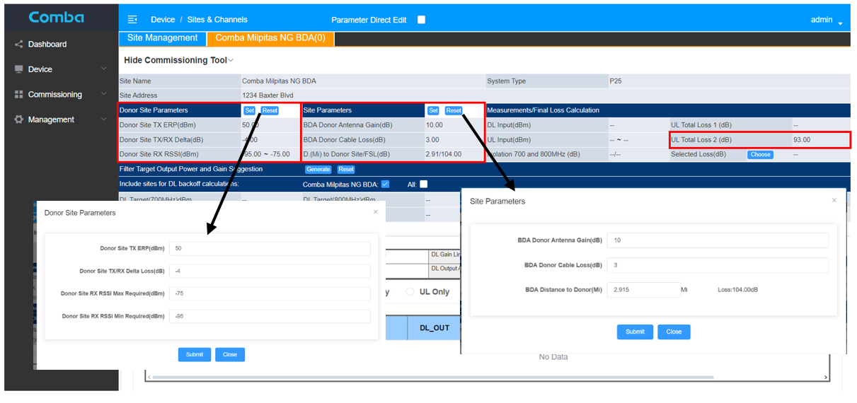
With this provided information, the BDA will calculate a theoretical uplink pathloss, in this example, 93dB is calculated.
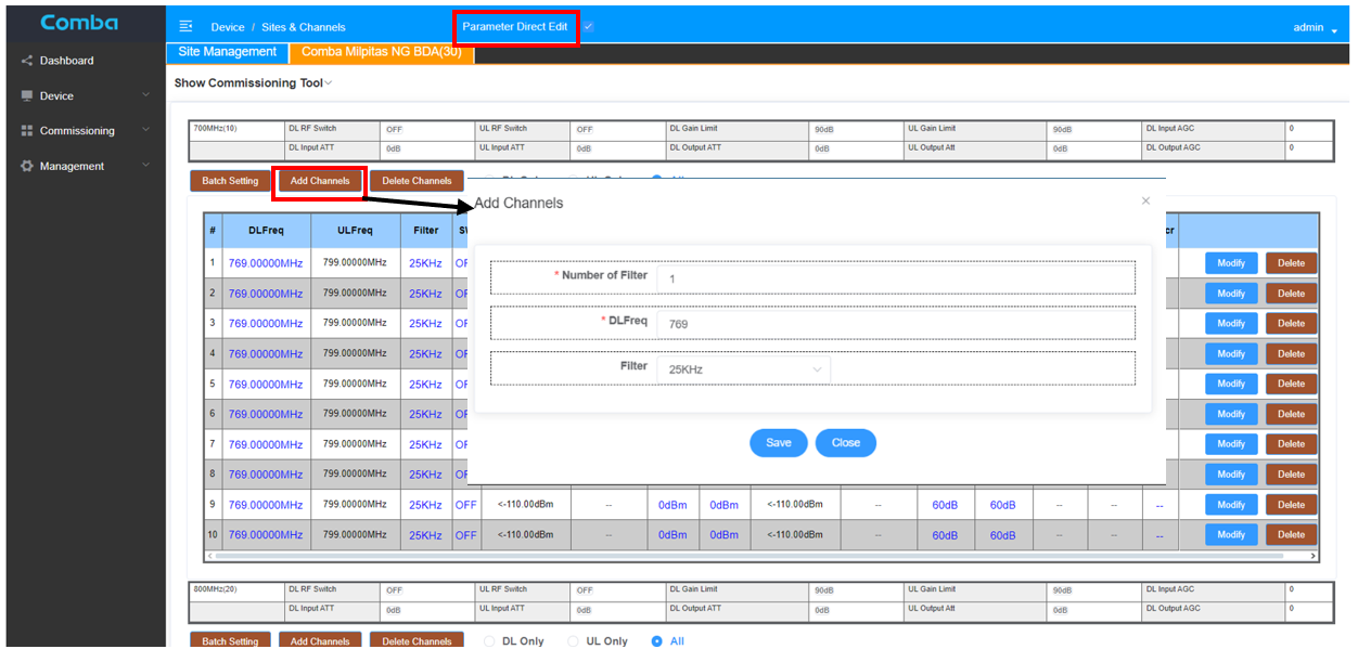
At this point, the frequency can be added by clicking the Add Channels button. Add number of filters, change filter size and click save. Comba recommends activating “Parameter Direct Edit” feature by clicking on the check box in the above header, then changing the frequencies directly by clicking on the “blue” writing. The uplink frequencies will be automatically populated.
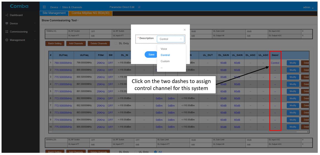
Target Power, DL& UL Gains, SW switch etc. should be changed at a later step, but for the DL input test, it is important to assign the control channel (multiple CC selection are possible) on this page.
4. Isolation Test
Under Commissioning/Isolation Check you can execute the isolation measurement.
This page will allow you to perform an automatic isolation check on the distributed antenna system (DAS) or manually enter collected test results that were performed on the DAS using a spectrum analyzer and signal generator.
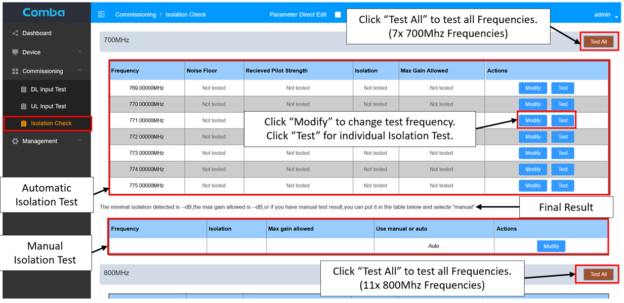
To use the automated isolation feature, the donor and DAS antennas must be connected to the BDA Donor Terminal (DT) and Mobile Terminal (MT) ports. The Isolation test frequencies are programmed into the BDA by using the Modify button. NOTE: The manually programmed frequencies must not be on-channel or adjacent-to active public safety channels, otherwise test results will fail or be distorted. Once the channels have been programmed, the user can press the Test All button, or test individual channels. When completed, the BDA will return isolation results including the maximum allowable gain in the GUI display.
5. Downlink Input Test
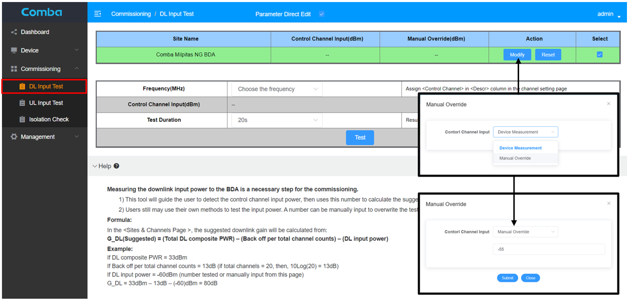
The Downlink Input Test feature will help calculate the suggested downlink gain value.
The user can select the following actions by using the Modify button:
· Device Management – Uses the programmed off-air control channel as an RF input source.
· Manual Override – Assumes a manually entered value based off a link budget design or other source.
The Reset button will clear the control channel or manual entry to initial values.
The system will use the programmed control channel as the RF input source.
Click on the “Choose the Frequency” dropdown menu and select the control channel to be used for off-air testing. NOTE: The user must identify the control channel in the Device/Sites & Channels/Channels Tab.
The Test Duration is defaulted to 20 seconds, but can be changed to 30, 40, 50 or 60 seconds, this will average the control channel over the preset timeframe.
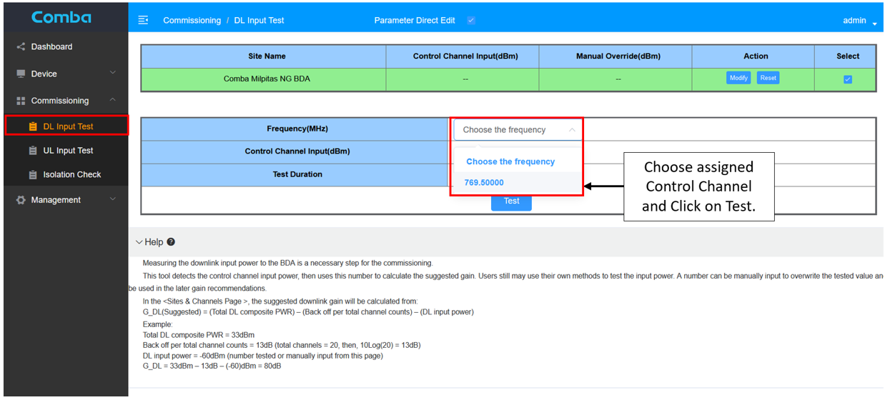
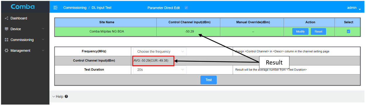
Click on the Test button to start the test. After the test duration the software will show the DL control measurements as shown below.
6. Uplink Input Test
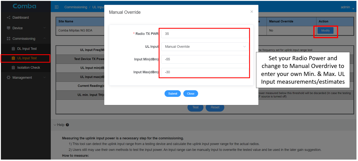
The UL plink test can be found under Commissioning/UL Input test. There are two options:
· Enter your own minimum and maximum uplink input measurements
· or use the BDA software to measure the minimum and maximum input signal. This would require a signal source like a CW generator.
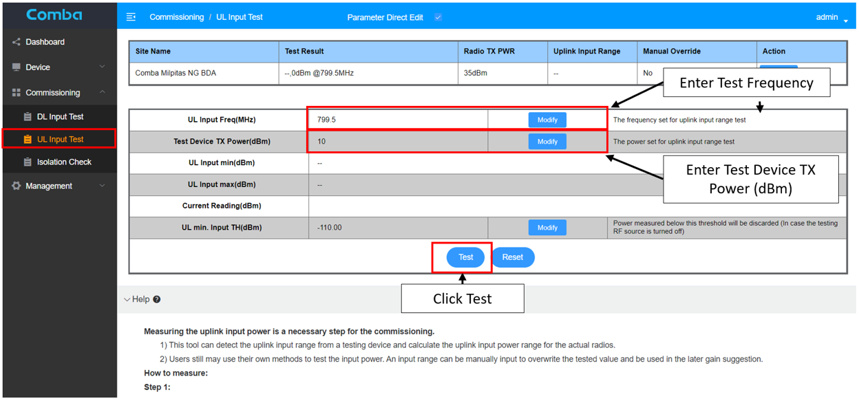
By clicking on Modify, shown in the picture below you can change to “Manual Override” and insert the manual min/max UL input measurements. Otherwise leave at “Device Measurement” to utilize the BDA tool to help measure minimum and maximum UL input. In this case you will also have to enter Radio TX Power. The software will need this information to calculate the power difference between the radio and the CW signal source later.
When using the software to measure the UL signal, the test frequency and also the TX power of the CW generator will have to be entered. Make sure to use a free/unoccupied test frequency! When the test equipment is set up with the same test frequency and ready, turn on the CW generator and click on Test in the software and wait for the countdown before starting to walk the building.
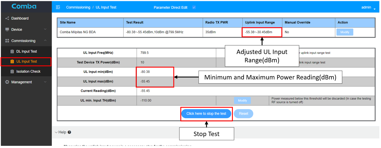
Please cover all areas in the building (close the DAS antennas, far away from DAS antennas, stairwells, Elevator lobbies, critical areas etc.). The BDA software will collect the uplink signals from the test device and begin to calculate the minimum and maximum values seen through the passive distributed antenna system.
Once the user has thoroughly walked the distributed antenna system, they will return to the BDA and click on the Stop the Test button.
Once stopped, this GUI will display the uplink input minimum and maximum values into the BDA. It will then use the calculated offset between the test device output power and proposed radio output power to display the Uplink Input Range.
7. Recommendations
Once the Downlink Input, Uplink Input and the Isolation Tests have all been calculated or manually entered, the next step is BDA gain recommendations.
To use the BDA recommendations, go to Device/Site & Channels/Site Channel tab, the commissioning tool window will be display above the channel lists. The measurements, automatically calculated or manually added, will be displayed in the Measurements/Final Loss Calculation window.
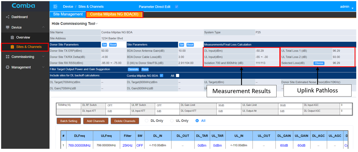
Two UL Total Link Pathlosses will be shown, where the user will have to select one of them.
· UL Pathloss 1 – This is the donor site transmit and receive delta (tower top amplifier) plus the difference of the donor site transmit power and the BDA receive power (Recommended)
o UL Total Pathloss 1 = TX/RX Delta + Donor Site TX ERP – Control Channel Input = -4dB + 50dBm – (-50.29dBm) = 96.29dB
· UL Pathloss 2 – Is calculated from donor site transmit and receive delta (tower top amplifier), Free Space Loss, BDA Donor Antenna Gain, and Donor Cable Loss
o UL Total Pathloss 2 = TX/RX Delta + Free Space Loss – Donor Antenna Gain + Cable Loss = -4dB + 104dB – 10dB + 3dB = 93dB
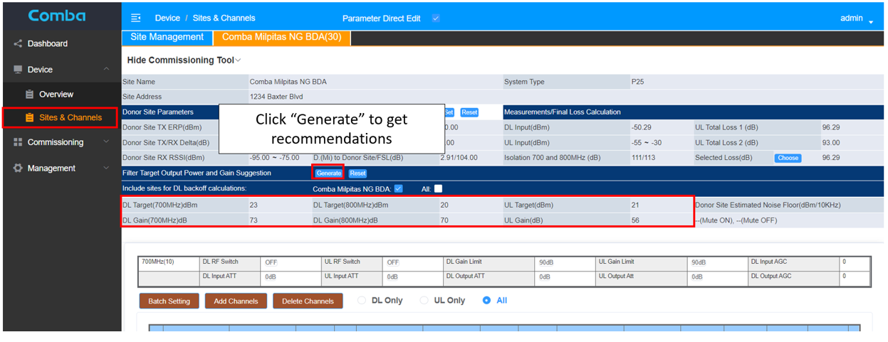
When the UL Total Pathloss is selected, click on the generate button to calculate the BDA recommendations. Once generated, the recommendations will populate in the window labeled Include sites for downlink backoff calculations. This will include Downlink and Uplink Target power levels, downlink and uplink channels gains.
If the user agrees to the calculated recommendations, they will have to manually add these recommendations to the individual channels.
NOTE: This completes the BDA automatic calculations and recommendations. We suggest that the user validates these recommendations with the design downlink and uplink link budget calculations.
8. Program and Turn On
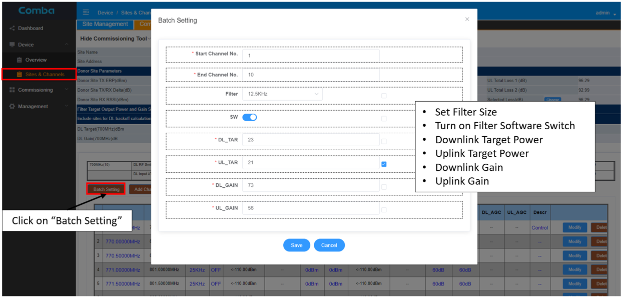
To use the recommended values from the commissioning software tool or the manually calculated values, select batch setting on the channel window under Device /Overview Sites/Channels and manually enter them, verify the filter size, turn on the channel RF switch and click on save.
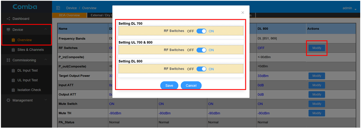
Once the channel information has been entered and channel switches turned on, go to the device/overview tab and click on the RF Switches modify button to turn on the downlink and uplink RF switches.
NOTE: Only turn on the RF switches with the permission of the local AHJ and/or licensee!
Conclusion:
By following these eight steps, the Comba V3 Class A BDA can be easily programed and commissioned. But as mentioned at the beginning of the process, Comba highly recommends that the individual performing the BDA commissioning conduct manual tests and compare the collected results to the Comba generated results to verify that no mistakes are made during the commissioning process.