Public Safety communications systems and networks, whether analog or digital in nature, inherently have the potential to suffer from time-delay interference (TDI). TDI is the byproduct of a radio receiver or DAS antenna receiving multiple “copies” of the same signal, but receiving them at different times. Every simulcast public safety network will introduce time delays (see the diagram on page 2). One cannot eliminate TDI just as one cannot eliminate random RF noise – but there are ways that the effects of delay can be controlled. Some delay is acceptable, but once it reaches a certain level, it can cripple system performance, endangering the first responders who rely on voice communications during emergencies.
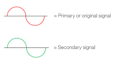
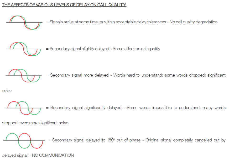
The following diagrams show graphically how TDI affects the signal quality – the RF signals are represented here as a waveform:
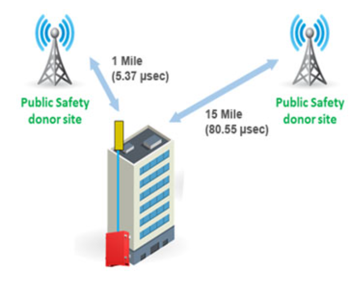
Radio signals can travel one mile in approximately 5.37µsec. As you can see from the diagram below, the signal from the closer donor site will reach the target building much earlier than the signal from the donor site that is farther away. However, there is always a chance that the signal from the farther away donor site will be strong enough to penetrate the building. If the First Responder radio is being used inside the building receives and attempts to process both signals (one being greatly delayed), the result will be TDI that will affect the call quality as described above.
And to make things even worse – if the building has an in building coverage enhancement system (called a Distributed Antenna System, or DAS), then there is a strong likelihood that the First Responder radio will receive and attempt to process all 3 signals (from the DAS, and from the 2 donor sites) – compounding the TDI situation and have even worse effect on the call quality.
Below, we examine a number of ways to mitigate TDI effects on the Public Safety DAS system in order to minimize the delay levels to an acceptable level.
The solution provider who is designing and installing the DAS should:
- Ensure that there is appropriate isolation between the service (interior) antennas that are installed in the building, either by adjusting the quantity and physical location of the antennas, and/ or by making adjustments in the signal levels delivered to the antennas as part of what is called “link budgeting”. A good design for 700/800MHz DAS systems calls for isolation of 47dB; UHF systems call for 42dB of isolation, and VHF calls for 33dB of isolation.
- Keep the system delay as low as possible. System delay within the DAS system can come from the active equipment – it can also stem from passive components like splitters, couplers – and especially from filters that may be required to accommodate the specific channel requirements. The majority of the 800MHz networks in use today are P25 Phase I or Phase II – these services require a maximum allowable delay between 15usec for Phase II to 33usec for Phase I.
Comba’s BDAs (Bi Directional Amplifiers) that are used in Public Safety DAS systems are available as Class A narrow band devices that can provide delays as low as 15usec, as well as Class B devices that can provide delay figures as low as 6.5usec. The solution provide who is deploying Comba BDAs will select the correct model (Class A or B) depending on several criterion, including the desired delay level.
- Design the DAS so that it either:
o Meets the maximum tolerable delay levels (through the methods described above)
OR
o If the best available delay level of the DAS exceeds the maximum figure that can be tolerated – the DAS must be designed to have “dominance” over the signal from the macro tower(s) that might be penetrating the building. This is accomplished by increasing the strength of the RF signal that emanates from the DAS antennas so that it is stronger than the RF signal from the macro tower that is penetrating the building – i.e., the DAS is “dominant” over the penetrating macro signal. (The 2 way radio receiver is designed to “reject” the weaker signal – thusly the weaker signal from the penetrating tower will not cause TDI problems.) This is accomplished by measuring the strength of the penetrating tower signal, and then calculating the how much stronger the signal from the DAS antenna needs to be.
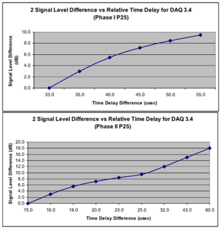
The charts below indicate the amount of signal level dominance required in order to overcome the TDI issues.
It is interesting to note that, irrespective of in-building DAS systems – the macro network can in and by itself suffer from TDI problems. Refer to the diagram on page 2 above, but imagine that instead of a building in between the two donor towers – it is a First Responder handheld or vehicle radio. If the radio receives both signals, but one is delayed, the negative effects on call quality as shown above will occur.
To minimize this “open air” TDI problem, the macro network designer and operators will attempt to design a network where the areas covered by the towers do not overlap. To accomplish, they will do one or more of the following:
- Determine the number of tower sites required to provide good coverage without overlapping each other
- Align the donor tower antennas horizontally (left to right) to more precisely align the coverage areas
- Adjust the tower antennas vertically (tilt up or down) to more precisely align the coverage areas
- Select the appropriate size transmitter for the towers (these typically range from 35 to 100 watts of effective radiated power (ERP)
- If the macro network is digital – then, an additional adjustment for overcoming TDI is to intentionally introduce delay on the signal from the closer tower so that it arrives at the same time as the signal from the tower that is farther away
In conclusion, TDI is inescapable, but knowing how to mitigate its effect can lead to a stable in-building public safety communications DAS system and ensure stable voice communications for First Responders.
Time delay calculation charts – from “National Public Safety Telecommunications Council (NPSTC) – Best Practices for In-Building Communications – Appendices A through E” – November 12, 2007