The National Fire Code bodies have adopted language that speaks to the use of amplification systems within buildings. While the model code requires minimum RF signal levels, it alludes to the use of amplification systems to solve low signal issues. The issue today, is that many AHJs (Fire Code Officials) have interpreted the code to mean that if a building is lacking adequate indoor public safety radio coverage, a signal booster, or BDA, must be installed. Because of this interpretation BDA ERRCS (Emergency Radio Responder Communication System) are popping up all over the United States. Due to the increase in the use of improperly designed or commissioned signal booster based ERRCs systems, interference complaints are increasing at an alarming rate. At minimum, a poorly implemented ERRCS system will cause communications difficulties on the network – if bad enough, it can put a network tower out of commission. In order to protect the integrity of the LMR (Land-Mobile-Radio) networks these systems are supposed to support, we must start using better engineering practices to assure as little macro degradation as possible.
Most system designs are based on downlink signal modeling with little or no regard to reverse link (uplink) design. While this type of modeling can be used in the commercial world it is disastrous when used in the public safety or ERRCS environment. The reason that downlink modeling is not only ineffective but dangerous, is because LMR radios do not use power control and the systems are typically unbalanced favoring the forward or downlink. Therefore, most systems that are designed using only downlink modeling end up with too few service antennas to support portable uplink operation.
FCC rule section 90.219, which is the law that gives authority to use BDAs, has some very specific guidelines for system design and use. These rules are designed to protect the macro environment from unnecessary interference and provide the tools to allow licensees to more easily track down interference if it occurs.
The first section of the rule speaks to Authority to Operate;
(b) Authority to operate. PLMRS (Private Land Mobile Radio Services) licensees for stations operating on assigned channels higher than 150 MHz may operate signal boosters, limited to the service band for which they are authorized, as needed anywhere within the PLMRS stations’ service contour, but may not extend the stations’ service contour.
(1) PLMRS licensees may also consent to operation of signal boosters by non-licensees (such as a building owner or a signal booster installation contractor) within their service contour and across their applicable frequencies, but must maintain a reasonable level of control over these operations in order to resolve interference problems.
(i) Non-licensees seeking to operate signal boosters must obtain the express consent of the licensee(s) of the frequencies for which the device or system is intended to amplify. The consent must be maintained in a recordable format that can be presented to an FCC representative or other relevant licensee investigating interference.
(ii) Consent is not required from third party (unintended) licensees whose signals are incidentally retransmitted. However, signal booster operation is on a non-interference basis and operations may be required to cease or alter the operating parameters due to a request from an FCC representative or a licensee’s request to resolve interference.
- c)Licensee responsibility; interference.PLMRS licensees that operate signal boosters are responsible for their proper operation, and are responsible for correcting any harmful interference that signal booster operation may cause to other licensed communications services. Normal co-channel transmissions are not considered to be harmful interference. Licensees are required to resolve interference problems pursuant to 90.173(b). Licensees shall act in good faith regarding the operation of signal boosters and in the resolution of interference due to signal booster operation. Licensees who are unable to determine the location or cause of signal booster interference may seek assistance from the FCC to resolve such problems.
In summary – the rule states that signal booster or BDA driven ERRCS systems can only be installed with the express consent of the licensee and, information specific to the deployment of the signal booster or BDA must be in recordable format. The rule requires that the licensee grant permission to the building owner to operate a signal booster. The licensee may not be the Fire Code Official (for example, the fire code official may represent a city who gets their radio service from the County who is the license holder). There is important precedence for this rule. First and foremost, the licensee is responsible for maintaining the integrity of the radio system so that First Responders can communicate; and second, the licensees have to maintain “reasonable control” over the operation of not only signal boosters but any RF device attached to their systems in order to resolve interference issue. Lastly, the licensee is charged with being able to deliver the consent document to the FCC or other relevant licensee that might be investigating interference.
The second section of the rule that must be understood is simply the noise power allowed from the signal booster/DAS system used for an ERRCS deployment.
(6) Good engineering practice must be used in regard to the radiation of intermodulation products and noise, such that interference to licensed communications systems is avoided. In the event of harmful interference caused by any given deployment, the FCC may require additional attenuation or filtering of the emissions and/or noise from signal boosters or signal booster systems, as necessary to eliminate the interference.
(i) In general, the ERP (Effective Radiated Power) of intermodulation products should not exceed −30 dBm in 10 kHz measurement bandwidth.
(ii) In general, the ERP of noise within the passband should not exceed −43 dBm in 10 kHz measurement bandwidth.
(iii) In general, the ERP of noise on spectrum more than 1 MHz outside of the passband should not exceed −70 dBm in a 10 kHz measurement bandwidth.
The issue that most often comes into play within the scope of this rule is related to noise power within the passband, and noise power 1 MHz outside the passband. It should be noted that these are system design requirements. It is the designer’s responsibility to make sure these are met. Noise power as defined in terms of ERP is a function of amplifier gain as well as donor coaxial run and donor antenna gain. Uplink noise crown measurements should be taken on every job to assure that the system meets the design requirements.
The third section of the rule is maximum power per channel.
(e) Device Specifications. In addition to the general rules for equipment certification in § 90.203(a)(2) and part 2, subpart J of this chapter, a signal booster must also meet the rules in this paragraph.
(1) The output power capability of a signal booster must be designed for deployments providing a radiated power not exceeding 5 Watts ERP for each retransmitted channel.
This section speaks not only to the equipment device specification but also to system design. The rule simply states that the amplifier must be built to support a maximum of 5 watts ERP per channel. System design must not exceed this power level. Most Signal Boosters are designed for uplink raw power of 31 dBm or less, thusly accounting for the use of a donor antenna with some degree of gain.
Now that we have the rules section cleared up, let’s examine the process that must be undertaken to design a system that meets the rules without causing unnecessary uplink interference.
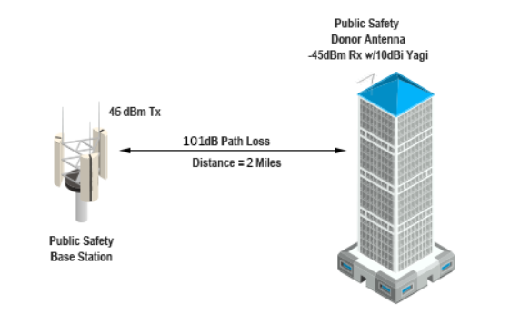
Initial planning of any Public Safety ERRCS communications network begins with the radio link budget. Because the uplink is usually the weakest link, one should start with it. An uplink analysis should be completed using a microwave path modeling tool or FS loss calculation. As with any type of radio link, all efforts should be made to maintain a line of site path between the location of the signal booster/BDA and the donor site. In the example below the building housing the signal booster/ BDA is located two miles from the donor site.
It is at this point that a full link analysis needs to be performed. This exercise will demonstrate proper service antenna spacing, estimated uplink BDA gain, and estimated noise power generated by the system design.
Maximum uplink noise output power as stipulated in the rule is -43 dBm ERP. This is the maximum noise power allowed to be radiated within the passband of the signal booster. Every licensee should go through the exercise of determining the maximum noise rise they will allow at any given site. From a practical perspective the calculated noise power delivered to any site should be at least 6 dB below the noise floor at the site.
Let’s review the following example: The theoretical noise floor is -133 dBm for a 12.5 KHz channel, so target noise power should not exceed -139 at the donor site. (Convert to 10 KHz BW to be consistent with the rule, Theoretical -134 and 140 dBm) In this example system we have a 101dB path loss. If we stay at the FCC specification, we will deliver a noise power to the donor site of -144dBm. More forward-looking licensees have defined the maximum calculated noise they will allow at their donor sites. Some licensees require a calculated noise power delivered to the donor site to be 15 dB below measured noise floor while others just use a fixed value calculation such as; calculated noise power delivered to any given donor site will not exceed -150dBm/10KHz BW. Regardless of how the licensee determines maximum noise level, this specification should be delivered to the design engineer in written form.
Uplink Noise Budget
First exercise: Determine the maximum uplink gain that can be used in any specific design under the rule.
Uplink noise can be estimated by taking the theoretical noise floor @ 10 KHz and adding amplifier gain, noise figure and donor antenna system gain. This will get you very close to the actual measured value. If the noise figure is not published, assume 9dB as that is what the Commission defines in the rule. (See the table below)
Estimated noise power ERP from a BDA
Noise floor | Amplifier Gain | Amp noise figure | Donor antenna gain less cable loss | Estimated noise Level ERP | |
-133 | 95 | 9 | 6 | -23dBm |
In the example above the estimated maximum noise level is about 20 dBm too high, which far exceeds FCC rules that allow -43dBm. This exercise demonstrates that in most situations you cannot run 95 dB of gain and still stay within the FCC rule.
Noise floor | Amplifier Gain | Amp noise figure | Donor antenna gain less cable loss | Estimated noise Level ERP | |
-133 | 72 | 9 | 9 | -43dBm |
In the example above the amplifier gain has been reduced, resulting in the estimated maximum noise level being reduced to -43 dBm, which is within the FCC rule requirements.
From a practical perspective the maximum gain of a BDA, signal booster or DAS system should not exceed 70 to 75 dB. This is the maximum gain that will allow most amplifiers to operate within the FCC noise rule. Signal boosters with lower noise figures can operate at higher gain.
All noise crowns should be measured and to confirm the expected levels. Noise crown measurements should be delivered to AHJ in close out package.
Second Exercise: Determine if the noise power delivered to the donor site will increase the noise floor at the site;
In our example @ -43 dBm noise power, with a donor site 2 miles away from the signal booster/BDA location, our estimated noise level at the site will be -144 dBm, calculated; see the table below.
Because this value is 11 dB less than the theoretical noise floor (-134 dBm), the BDA will not significantly affect the noise floor at the donor site. However, multiple BDAs pointing at a single sector or site will have an additive noise effect. Therefore, the licensee should inform the integrator of the maximum calculated noise level allowed at any given site. This should be part of the AHJs technical document.
Signal Booster/BDA Noise ERP | PATH LOSS | Calculated Noise power@ donor site |
-43 dBm | 101 dB | -144 dBm |
Now that we have the noise issue out of the way, and the licensee has agreed to let us deliver a calculated -144dBm noise to the site we can move on to our signal link budget.
Signal Link Budget
Let’s assume that our signal booster/BDA has a maximum uplink power of 27 dBm.
The uplink gain value here is based on two aspects of the system design.
First, the passive component loss on the service side of the system. While passive component losses to all service antenna legs should be approximately equal, the actual value used in the design should be taken from the antenna leg that is electrically closest to the signal booster. In our example we will use 30 dB.
The second is the target distance to any service antenna. Use the value where a subscriber unit (SU) gets closest to an antenna in normal operation. In our example we will use 10 feet.
We now can determine the maximum gain value we can use to produce full power out of the signal booster/BDA when the SU is at its closest point to any antenna. In the example case the signal booster/BDA gain should be set to about 63 dB. If the gain is set any higher than this the signal booster will be forced into AGC or OLC to protect its integrity. This will lower the gain of the signal booster and cause near/far issues. The AGC or OLC should be used to handle unusual activity such as a person on a ladder right next to an antenna or a high-power mobile radio coming into proximity of an antenna in a garage area etc. Incorrect uplink gain setting is the biggest contributor to high noise problems and overall poor performance than any other aspect of a signal booster/BDA/DAS project.
SU OUTPUT POWER | PASSIVE COMPONENT LOSS | SIGNAL AT SERVICE ANTENNA 10 FOOT | SU SIGNAL @ BASE OF BDA | BDA GAIN | BDA OUTPUT POWER | 10 dB donor gain ERP |
36 dBm | 30 dB | -6 dBm | -36 dBm | 63 | 27 dBm | 37 dBm |
Now we can look at estimated signal at the donor site. This will determine the service antenna spacing that must be used in the project. Based on our link budget the estimated signal levels at the donor site are as follows:
Channel Power at donor site: (Note, this has nothing to do with noise power delivered to the site)
Signal Booster/ BDA ERP | PATH LOSS | SIGNAL AT DONOR SITE |
37 dBm | 101 dB | -64 dBm |
6 dBm | 101 dB | -95 dBm |
The delta between our maximum signal and minimum signal at the donor site will determine antenna spacing. In this case 31 dB. If your downlink iBwave design shows signal variance greater than 31 dB, throw it out and start over. (See examples below of an actual design.)
We can also calculate our expected uplink noise value to the site. Note that we have decreased output noise power to -53 dBm by reducing the overall system gain (see the table below). You will see that this delivers an even better noise level than the FCC standards of -43 dBm.
Noise floor | Amplifier Gain | Amp noise figure | Donor antenna gain less cable loss | Estimated noise Level ERP | |
-134 | 63 | 9 | 9 | -53dBm |
Signal Booster/BDA ERP | PATH LOSS | NOISE AT DONOR SITE |
-53 dBm | 101 dB | -154 dBm |
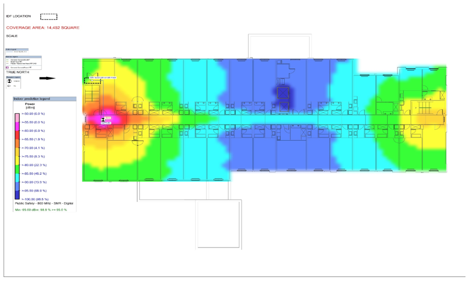
Examples of Bad and good BDA designs:
BAD DESIGN –Too few antennas to support uplink while downlink design looks okay.
Downlink looks somewhat okay but notice the variance of signal on the floor. -50 dBm at the antenna and -95 in the blue area. This is a variance of 45 dB, our link budget only allows for 31 (reference the table above – BDA ERP).
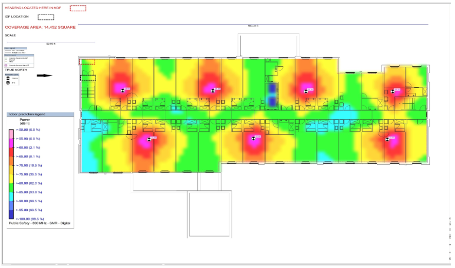
GOOD DESIGN – Proper service antenna layout
Note antenna count went from two to seven. This design will support uplink with no near far issues while NOT causing noise issues – because the design does not necessitate running the BDA at gain levels that produce noise in excess of FCC rules.
Summary and notes:
- The FCC defines a BDA or signal booster as; A device or system that automatically receives, amplifies, and retransmits signals from wireless stations into and out of building interiors, tunnels, shielded outdoor areas and other locations where these signals would otherwise be too weak for reliable communications. DAS systems may contain both Class A and Class B signal boosters as components. A signal booster or BDA is not part of the fire alarm system, it is an extension of the public safety LMR system and is governed under Part 90 of the Federal Communications Commission rules. A signal booster is essentially an extension transmitter that has special licensing provisions outlined in FCC rule section 90.219.
- Only the licensee can grant permission to use a BDA, Signal Booster or DAS to enhance public safety radio communications.
- FCC rules outline the maximum noise levels of these systems. In general noise levels should not exceed -43 dBm ERP/10 KHz BW. The FCC can require more stringent specifications if a signal booster causes interference.
- Proper link budgeting on the front end of system design can virtually eliminate the possibility of a BDA causing interference in any given environment.
- Under NFPA and IFC fire codes the systems shall be designed to operate multiple channels under reduced gain situations. This should be demonstrated in front end system design prior to system build. (Note: good system design will very rarely produce a reduced gain situation)
- Early code requirements required the use of the minimum amount of gain necessary. This rule of thumb should always be followed
- Under normal circumstances uplink BDA gain should not exceed 75 dB of gain. In most designs signal booster/BDA gain should be between 60 and 65 dB of gain depending on passive loss and antenna location. All signal booster noise crowns should be measured with signal booster active and all squelch circuits disabled. Some signal boosters do not actually reduce gain but add attenuation thus the noise levels stay at a fixed level no matter the gain setting. This can be easily demonstrated by placing a dummy load on the service port of the signal booster and if the unit has squelch, disabling the squelch control. Below are a few examples of signal booster noise crowns.
- While the use of squelch circuits does not negate the need to keep noise components under -43 dBm it should be noted that some DSP technologies may allow for a signal booster or DAS amplifiers to operate on one channel and not create excessive noise in the remainder of the system passband. It is the responsibility of the integrator to assure that noise levels on an active amplifier do not exceed -43 dBm within the passband when the amplifier is active.
Uplink Noise Crown Examples
All BDAs terminated on both service and donor ports.
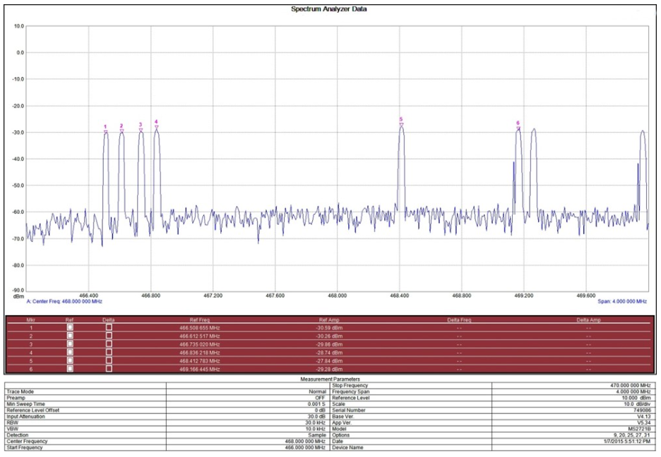
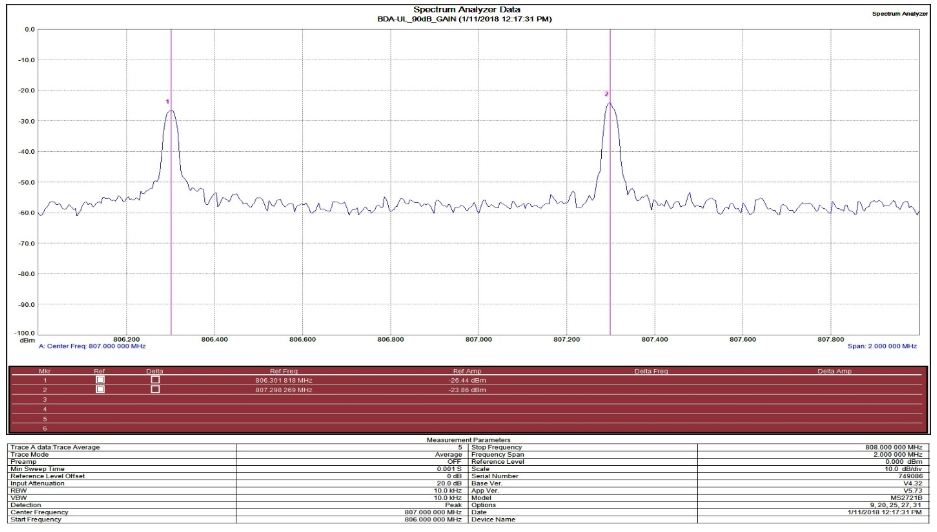
Example 1 – Channelized digital BDA
466-469 MHz Broadband noise level is approximately -60 dBm. Channel output filter levels approximately -30 dBm. Gain set at 95dB. Spectrum analyzer RBW 30 KHz.
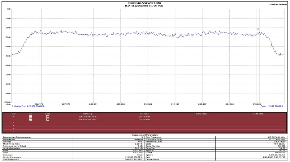
Example 2 – Channelized Digital BDA
Broadband noise crown -57 dBm. Channel filter noise crown -27 dBm. Gain set at 90 dB
Example 3 Broadband Amplifier
Broadband noise crown -27 dBm. Gain set at 90 dB
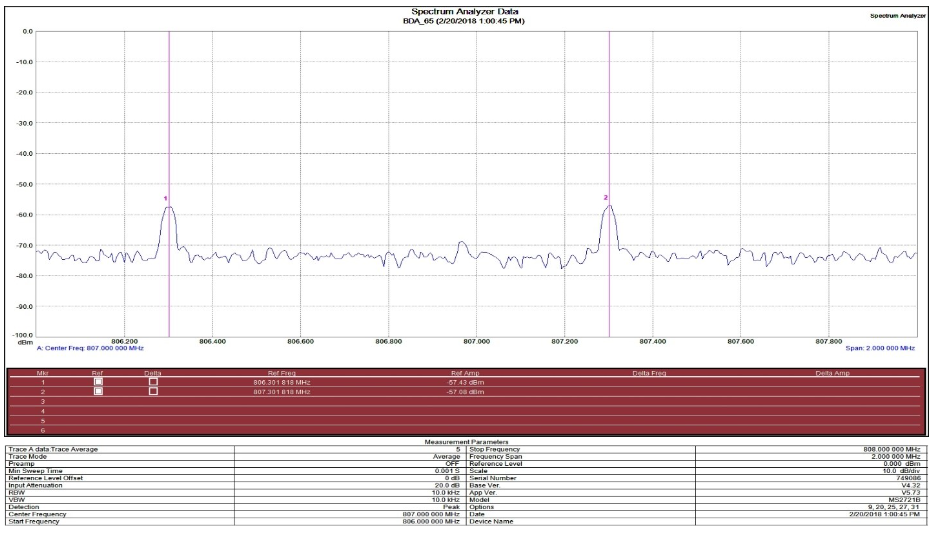
Example 4 – Channelized Digital BDA
Broadband noise crown -75 dBm. Channel filter noise crown -58 dBm. Gain Set at 60 dB