There are several reasons why combining Public Safety and Commercial (Cellular) active DAS may not be the best choice, as discussed in my Jan 2018 Tech Brief on “Why Public Safety Convergence is History”. However, in certain applications, a common passive DAS might be a practical and cost-effective choice. Colocations filters are a must for combined passive DAS solutions, but before you venture down that road be sure to check with your Authority Having Jurisdiction (AHJ) for confirmation on whether code will allow shared passive DAS.
Before jumping into the mechanics of how to use colocation filters, let’s first discuss why we need them. As the name implies, these filters are used when a Public Safety and Commercial in-building DAS systems are to be collocated within the same building. Whether on separate DAS or combined, some level of additional filtering is usually required to avoid interference between the two. An exception might be in cases where approximately 60dB or more isolation can be maintained between the DAS’. This may prove challenging to find sufficient real estate where placement of indoor antennas from separate DAS are not line-of-sight of each other. Depending on the gain of the antennas and openness of the environment, this may mean spacing antennas >100 ft.
The two bands of concern are Verizon’s 700 MHz upper C-block (uplink band 776-787 MHz) and 850 MHz cellular band (uplink 817-849 MHz). In both cases, uplink communications into the cellular remote units can be desensed by the Public Safety in-building system when sharing a common passive DAS, or in separated DAS that lack sufficient isolation.
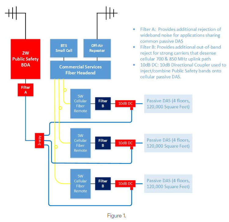
Two types of colocation filters are required: a wideband noise reject filter, and a strong carrier signal reject filter. The “wideband noise” filter attenuates out-of-band noise, which is inherent with all amplifications devices. Wideband noise must be attenuated at the output of the Public Safety device, whether it be a BDA or a Public Safety fiber remote unit. Refer to “Filter A” in Figure 1. for placement of wideband noise reject filter. Once the noise reaches the commercial DAS, it is considered in-band and can no longer be attenuated without also attenuating desired cellular channels.
The “strong carrier” filter is placed in-line with each commercial fiber remote and is designed to reject the out-of-band strong carriers generated by the downlink of the Public Safety BDA or Public Safety fiber remote. Refer to “Filter B” in Figure 1. for placement of the strong carrier reject filter.
Now that we’ve touched on why we need these filters, let’s discuss the impact they will have on your DAS design. Each filter introduces loss into the system and loss effects coverage. Typical losses are around 1-2dB at the upper bands >1GHz, and 4-5dB at the lower bands. The good news is that most commercial DAS designs are modeled around coverage at the PCS and AWS bands where cable losses and propagation characteristics are more limiting than the lower bands. Consequently, the lower bands generally have plenty of margin to absorb 4-5dB of attenuation introduced by these filters, assuming equal output power at all bands.
Word of Caution: Some suppliers of cellular DAS product recognized the advantage of this coverage disparity between upper and lower bands and have addressed this by packaging lower power amplifiers for lower bands and higher power amplifiers for upper bands into their fiber remotes. It’s safe to state that in a shared DAS, 700MHz and 850MHz amplifiers with output powers up to 6dB lower than the upper PCS/AWS bands will still produce favorable results. This statement may not apply in all scenarios, so I encourage scrutinizing link budgets closely before designing a shared DAS using fiber remotes with unequal output powers.
The following example assumes all cellular fiber remotes have equal output power per band.
Figure 1 below is a system block diagram showing the placement of colocation filters for a shared passive DAS system. The diagram depicts the actual configuration used in the iBwave design, which was used to generate the heatmaps which are also included.
The following design parameters were used to model the system and visualize the coverage impact resulting from the addition of colocation filters.
- 12 Story building
- Each floor 30K square feet
- Total square footage 360K
- High Density RF environment
- 24 Channels @ 800 MHz Public Safety band
- 2 Channels @ 700 MHz LTE band
- 3 Channels @ 2100 MHz LTE band
- 5 Watt cellular remote units
- Each cellular remote serves 4 floors for a total of 120K square feet of coverage per remote
- 1 each, 2 Watt 800 MHz Public Safety BDA serving entire building.
All floorplans in the example building are considered to have same layout and propagation characteristics. For this reason, the following heatmaps apply to the same floor.
Let’s start by showing the AWS, 2100 MHz LTE heatmaps, which as mentioned above, is one of the upper bands that limits coverage and typically dictates the overall design layout. The first AWS heatmap shows LTE coverage using 6 antennas with no colocation filter and no Public Safety services added:
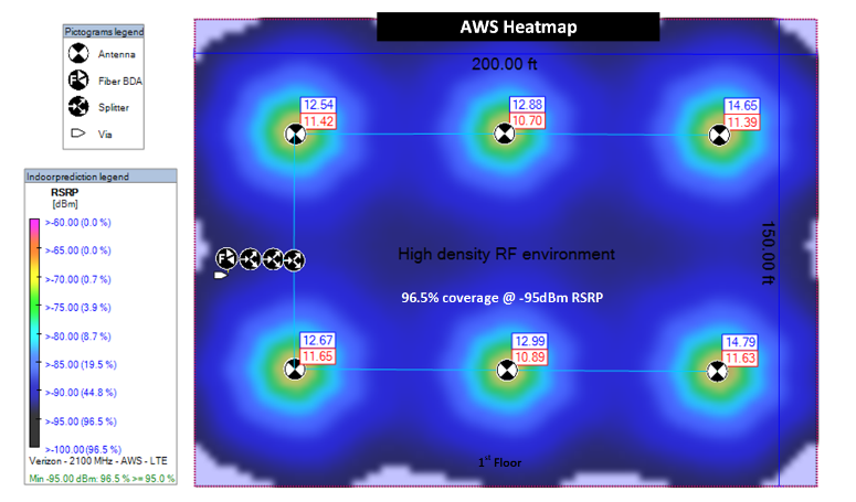
Notice in the legend that at least 96.5% of floor meets the -95dBm RSRP design criterion. Design requirements may vary between operators and regions.
Now let’s add colocation Filter B into the link budget.
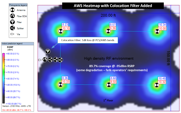
Adding 1dB plus jumper losses reduces coverage to 89.7%. Not bad, but some reconfiguration of design may be required for operator approval.
Now let’s add the 10dB directional coupler to the link budget which is necessary to complete the shared DAS design. Refer to the “10dB DC” red component in Figure 1, placed directly after Filter B. A 10dB coupler was selected to minimize the impact on the commercial DAS while meeting coverage requirement for Public Safety system as dictated by AHJ. System Designers often select 3dB hybrid devices for combining Public Safety and Cellular DAS. While this is an acceptable design approach, the results might leave you with an over-designed Public Safety system and call for more cellular remotes than otherwise necessary. In this example, the use of a 10dB Directional Coupler offers the best balance.
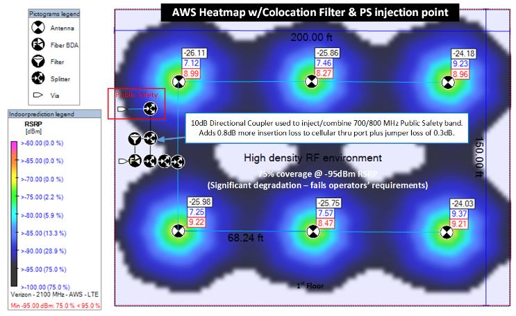
The additional losses from the filter + 10dB directional coupler + RF jumper cables results in coverage degradation to 75%. At this level of degradation, a forth fiber remote unit will be required to meet the 95% coverage at -95dBm RSRP.
YOU CAN STOP READING NOW: We have reach the focal point of this article: A shared DAS will require colocation filters; filters do add loss, loss adversely affects coverage. A shared passive DAS will add cost, but that additional cost may still be lower and esthetically more desirable than implementing a separate passive DAS.
AHJ’s arounds the country are adopting and enforcing local and National building codes which require proof of coverage for our First Responders in new construction, and in some cases existing buildings. Cellular inbuilding coverage is viewed as a forth utility, consequently collocation of Public Safety and Commercial DAS is on the rise. Don’t forget the colocation filters.
STILL A SKEPTIC? READ ON: If you’re curious about the impact on 700 LTE commercial service and Public Safety due to the high insertion losses from the colocation filters, the following heatmaps should provide the confirmation you’re looking for.
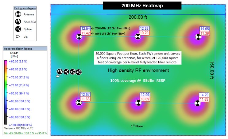
Using the same progression of heatmaps shown for the AWS band above, let’s see what happens to the 700 MHz coverage as we add the filter, RF jumpers and Public Safety injection point. The first heatmap below shows normal 700 MHz coverage, i.e., no filter, RF jumper, or 10dB directional coupler losses. The system is considered a “hot” system, as is expected when designing for AWS coverage and amplifier output powers are similar. In fact, we still have 99.1% coverage even at -80dBm. This would suggest that we have at least a 15dB margin to work with when adding filters losses.
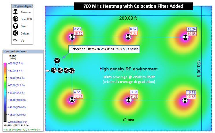
In this next heatmap, we add the filter and one extra RF jumper. Recall that in the lower bands the colocation filter loss increases to 4dB. Notice the 99.1% coverage at -80dBm went down to 91.9%. So, while we see some impact from the filter, we still have considerable margin before our reference signal dips down to -95dBm.
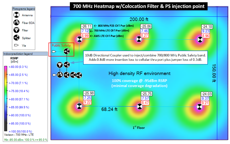
We mentioned previously that the 10dB directional coupler was the best ratio to balance impact on the commercial services system, yet low enough loss to ensure that the Public Safety system still met AHJ’s coverage requirements. The next heatmap adds 0.8dB loss introduced by the directional coupler and loss from one more RF jumper cable. The -80dBm coverage threshold goes down to 57.1%, however, we are still around 99.5% coverage at -85dBm, which is well above our minimum design threshold of -95dBm RSRP.
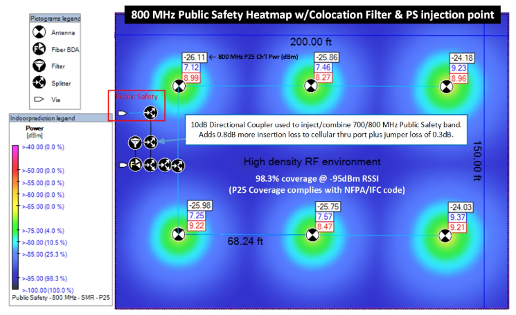
Now for the real test. What about the 800 MHz Public Safety system that is subjected to the 10dB coupling loss? As mentioned previously, the 10dB directional coupler was the best ratio to minimize impact on commercial services, yet low enough loss to ensure that the Public Safety system still met AHJ’s coverage requirements. The next heatmap includes the 10dB loss introduced by the directional coupler, plus the Public Safety “wideband noise” Filter A, plus the RF jumpers.
AHJ’s have widely adopted threshold -95dBm over 95% of the coverage area as acceptable for Public Safety in-building systems. The following heatmap show 98.3% coverage at 95dBm, which passes most NFPA/IFC code as well as local ordinances and AHJ mandates.
Here’s the take-away: A 2W Public Safety BDA subjected to 4dB of wideband filter attenuation, and 10dB of directional coupler attenuation, and 5dB of splitter loss, can still provide comparable coverage to a commercial services DAS configured with three 5W fiber remotes.
One caveat: Not all applications are cookie-cutter, 12-story buildings like what is represented in this example. Results can vary drastically depending on propagation characteristics of the building and physical layout.
In summary:
- • Don’t shy away from sharing the passive portion of a commercial DAS with a Public Safety coverage system if local codes allow for it.
- • Colocation filters will be increasingly important going forward. Know when and where to use them effectively.
- • 10dB Directional Couplers for use as Public Safety injection point are generally better that 3dB Hybrid devices.
- • If contemplating the use of commercial fiber remotes with un-equal output powers confirm lower bands can tolerate the extra losses induced by colocation filter and attenuation.
- • 2W power rating for Public Safety BDA’s and fiber remotes is a wise choice when colocations filters are to be used. Colocation filters can add $1500-$2000 per locations. Lower power alternatives will require more filters.
- • The benefit of combining commercial and public safety passive DAS system can be a practical and cost-effective choice to separate systems.
Comba offers Public Safety Fiber DAS product for larger applications where the BDA can no longer provide reliable communications. If you have questions regarding whether a shared passive DAS is right for your application, Comba’s engineering team would love to hear from you. Let’s talk.