SPECTRUM
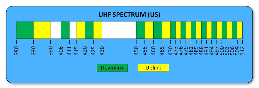
This article is specific to US frequency bands and their uses amongst the Public Safety in-building radio coverage enhancement community. The UHF (Ultra High Frequency) band spans from 380-512MHz, exception being the 420-450MHz band, which is an Amateur Radio band and generally excluded from in-door RF coverage enhancement.
380-400 MHz – Allocated exclusively for Federal Government use
400-420 MHz – Allocated for both Federal and non-federal use, such as Industrial/Business radio service
450-470 MHz – Land-Mobile Radio band. Allocated for use by Police, Fire, Government, business, and other 2-way radio services.
470-512MHz – UHF Television channels 14-20, also commonly referred to as T-band by LMR users. The following list of 12 urbanized areas are permitted by FCC to share this band for Public Safety radio communications:
Boston, MA Los Angeles, CA
Chicago, IL Miami, FL
Cleveland, OH New York, NY/N.E. New Jersey
Dallas/Fort Worth, TX Philadelphia, PA
Detroit, MI San Francisco/Oakland, CA
Houston, TX Washington, DC/Maryland/Virginia
FREQUENCY SEPARATION
The term separation is used to describe the offset between a channel pair’s transmit and receive frequencies in a full duplex mode. The greater the separation between the TX and RX frequencies, the more efficient and less expensive it is to produce filtering. For example, the cost to produce a duplexer for the T-band (470-512 MHz) with only 3 MHz separation could be 2 to 3 times more costly than a duplexer used in for the Military band (380-400 MHz) which has 10 MHz separation.
The table below lists the separation for each band and its general use.
Downlink Band | Uplink Band | TX-to-RX Separation | Use |
380-385 | 390-395 | 10 MHz | Federal LMR Band – Military |
385-390 | 395-400 | 10 MHz | Federal LMR Band – Military |
406-411 | 415-420 | 9 MHz | Government Land Mobile |
420-425 | 425-430 | 5 MHz | Canadian border areas |
450-455 | 455-460 | 5 MHz | Public Safety & Industrial/Business |
460-465 | 465-470 | 5 MHz | Public Safety & Industrial/Business |
470-473 | 473-476 | 3 MHz | Public Safety – Chicago, Cleveland, Los Angeles, Miami, NY, N.E. NJ, Pittsburg, Boston |
476-479 | 479-482 | 3 MHz | Public Safety – Chicago, Cleveland, Detroit, NY, N.E. NJ, |
482-485 | 485-488 | 3 MHz | Public Safety – Cleveland, Dallas/Fort Worth, Detroit, San Francisco/Oakland, Boston, Las Angeles, New York |
488-491 | 491-494 | 3 MHz | Public Safety – Houston, San Francisco/Oakland, Washington DC/MD/VA |
494-497 | 497-500 | 3 MHz | Public Safety – Pittsburg, Washington DC/MD/VA |
500-503 | 503-506 | 3 MHz | Public Safety – Philadelphia, |
506-509 | 509-512 | 3 MHz | Public Safety – Los Angeles, Philadelphia, |
PASSBAND/GUARD-BAND
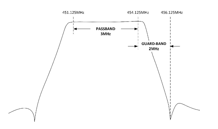
Passband indicates the width of the passband, which is determined by the span between lowest TX to highest TX frequency. For example, if an application has 5 frequency pairs and the lowest frequency in the TX group is 451.125 and the highest frequency in the group is 454.125, then the passband is 3MHz.
Guard-band is a term used to indicate the amount of frequency separation between the highest transmit frequency and lowest receive in the application. Using the same “3MHz Passband” example above, we can determine guard-band by looking at the separation, or TX-to-RX channel pair offset. Referring to the table above, we see that the separation is 5MHz for channels pairs that fall within the 450-470 MHz band. From this standard offset, we know the associated RX frequency for our lowest TX frequency is 456.125MHz (451.125MHz + 5MHz).
As shown in the following frequency plot, the delta between the highest TX in the passband and the lowest frequency in the RX band defines the guard-band. In this example, the guard-band is 2MHz.
Why is this information necessary?
As a manufacturer of bi-directional amplifiers and other in-building wireless communication equipment, we often receive customer requests for challenging frequency arrangements. It’s important for our customers to realize that while most of these requests can be satisfied, the wider the passband, and hence the narrower the guard-band, the more costly, larger, and possibly the more prone to intermod the solution. Not to mention, lead-time could exceed 8 weeks for custom filter builds.
FILTER REJECTION
Most of us are aware of the recent changes to the IFC National fire code that requires systems implementations maintain at least 20dB more isolation than system gain. This requirement is to project the “system” from oscillating. This same design concept applies to the internal workings of how the bi-directional amplifier (BDA) product operates. A BDA with 90dB of downlink gain will require at least 110dB is isolation (rejection) against the uplink band to maintain stability and not oscillate.
The UHF band is very different from the 800 MHz Public Safety band in that is does not have a set guard-band. The 800 MHz Public Safety band has a fixed guard-band of 35MHz (lowest TX to highest RX: 851MHz-816MHz=35MHz). The UHF band essential has no designated guard-band as the uplink and downlink paths are contiguous. For this reason, manufacturers of UHF products do not offer a one-size-fits-all type product.
Different regions of the US use different sub-bands, as we saw in the table above. And within each sub-band, different channel pairs are used, which can create a multitude of filters options.
Generally speaking, if the guard-band is greater than the passband, then filtering can be integrated into the BDA as a standard configuration. Several BDA manufacturers offer a “simplex” version of their BDA’s, which are designed to accommodate more challenging passband/guard-band configurations. The term “simplex” in this context means the BDA is configured with separate uplink and downlink paths, i.e., no internal duplexing/combining of bands. These simplex configurations allow oversized filtering to be placed external to the BDA making it easier to satisfy virtually any passband/guard-band scenario. Bear in mind that external filtering will likely have to be code compliant, meaning NEMA4 enclosure or cabinet(s) may be required. Check with your local Authority Having Jurisdiction (AHJ) to be sure external filtering is permitted.
INTERMOD
Intermod (IM), short for intermodulation, occurs when two or more frequencies mix and produce new frequencies. This mixing can occur in the BDA, or in any passive RF junction within the DAS network. The mixing coefficient of the junction determines the severity of the IM mix. Most manufacturers of BDA product use quality components to minimize the effects of IM, however, once RF signals make their way onto the passive DAS, it is the responsibility of the systems integrator to select quality couplers, splitters, and antennas to mitigate potential mixing. These passive components typically have a Passive IM, or “PIM” specification associated with them.
There are numerous white papers and articles available online that discuss the effects of PIM and how to mitigate, however, for simplicity sake, suffice it to say that passive components used in Public Safety DAS with a minimum PIM spec of -153dBc are acceptable for most low-power BDA applications.
It’s good practice to run an IM study for all UHF band BDA applications to confirm that frequencies are compatible. If low order IM products are revealed in the study, then serious consideration should be given to removing the offending frequencies from the mix, or at least notify customer of potential for harmful IM to limit liability.
The following is an example of IM study that reveals a 3rd order IM product that falls directly on frequency to the receive frequency 458.0125MHz.
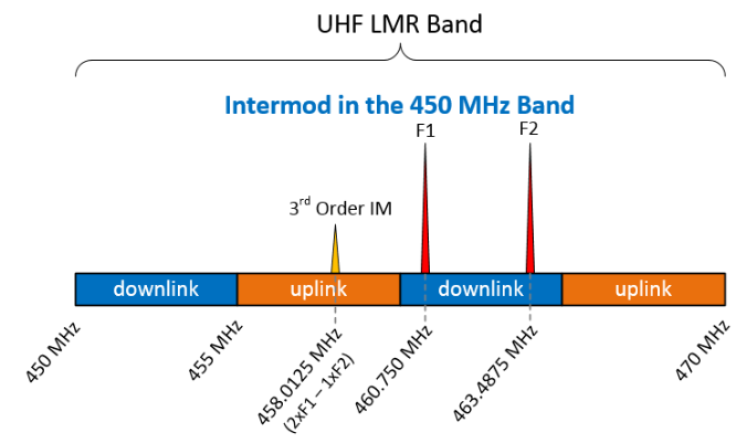
In this example, if the first splitter after the BDA had a PIM rating of -153dBc, then the following calculations can be used to estimate the amplitude of the harmful product:
Assuming the composite power of the BDA is 2 Watts, and both transmit frequencies involved in the mix are evenly sharing the amplifiers power at 1 Watt, then one might think that the IM product would be approximately -123dBm (+30dBm – 153dB). Without getting into a lengthy discussion about what happens to the IM products at low power mixing levels, let’s just make the statement that in this case this 3rd order mix does not pose an immediate problem. However, it is still good to record the potential for this mix simply because over time, connectors corrode, connections may loosen, or RF jumpers may deteriorate.
Now let’s consider a hypothetical “extreme case” using a high-power BDA producing 20 Watts per channel, or 43dBm, and instead let’s use a splitter with only a 140dBc PIM rating. The amplitude of the mix in this scenario is -97dBm (+43dBm-140dB). Given that most in-building Public Safety Emergency Responder Radio Communication Systems (ERRCS) require system performance meet -95dBm minimum, this system would likely not pass because of poor signal to noise ratio. Generally, we need approximately 17dB signal-to-noise ratio (SNR) to meet Delivered Audio Quality (DAQ) of 3.0, which is also an ERRCS requirement. In this high-power example, the resulting SNR is only 2dB (97dBm -95dBm). In this scenario, we would require the first splitter in the system to have at least a -155dBc PIM rating to minimize IM potential.
In summary, the UHF band includes several sub-bands which are distinguishable by the TX-to-RX channel separations. The smaller the separation, the more challenging the filter requirements become. As passbands increase and guard-bands decrease, filter size and cost go up. It is not uncommon for filtering to be placed external to the BDA for challenging frequency configuration.
Understanding the passband and guard-band requirements of your application can go along way when communicating project details with your equipment manufacturer.
Comba offers a variety of standard and customized single-band, dual-band, Class A or Class B UHF BDA products. A complementary Intermod Study is available upon request.