Understanding Dry Contact Terminology and How It Applies with Respect to the Bi-Directional Amplifier (BDA), Battery Backup Unit (BBU) and Fire Alarm Control Panel (FACP) Equipment
INTRODUCTION:
The purpose of this document is to help System Integrators understand the basic terminology of Dry Contacts and how they are applied in the Public Safety field with relationship to connecting Bi-Directional Amplifiers (BDAs), Battery Backup Units (BBUs) and Fire Alarm Control Panels (FACPs) to each other. Document includes Comba equipment screenshots for reference.
TERMINOLOGY:
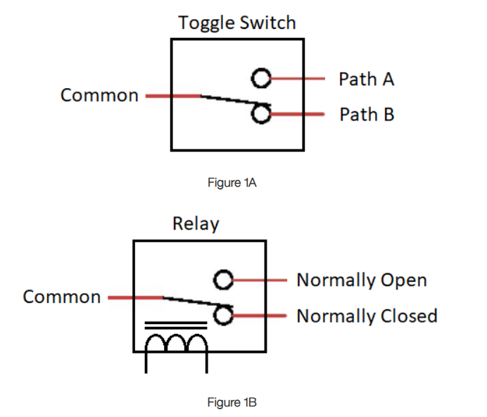
Single Pole Double Throw (SPDT) Circuit – A switch that has a single input terminal (Common) and can connect between one of two output terminals (Path A or Path B). It can serve as an on-off switch, and depending on how the circuit is configured, it can control two different circuits with the same input. The circuit can either be operated manually, i.e.- toggle switch (Figure 1A), or integrated with an electromagnetic coil, i.e.- relay (Figure 1B).
Dry Contact – A Dry Contact is when the power source at the relay contact terminals (Common, Normally Open or Normally Closed) is completely independent of the relay coil circuit. In the case of a BDA or BBU, these devices will control the relay coil circuit when an event occurs, i.e.- an alarm, thus toggling the respected relay contacts.
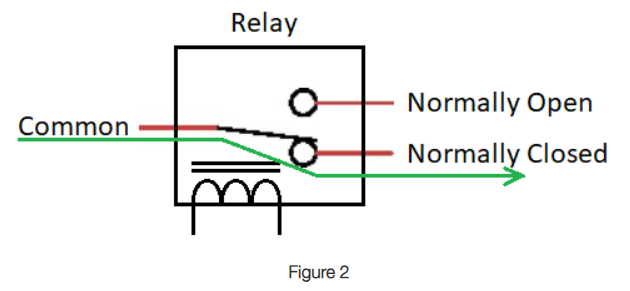
Normally Open (NO) – As shown in Figure 2 below, the contact is in the Normally Closed (NC) position and WILL NOT ALLOW current to pass between the Common and Normally Open (NO) terminals, i.e.- Open Circuit.
Normally Closed (NC) – As shown in Figure 2 below, the contact is in the Normally Closed (NC) position and WILL ALLOW current to pass between the Common and NC terminals, i.e.- Short Circuit.
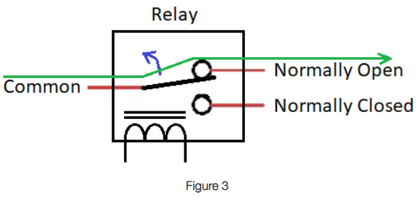
When the relay changes “state”, the NO and NC terminals will reverse direction, NOW ALLOWING the current to pass through the Common and NO terminals, thus creating a Short Circuit, but WILL NOT ALLOW the current to pass through the NC terminals. See Figure 3 below.
Normally Open Vs. Normally Closed with reference to an “energized” relay (device in alarm) and the Fire Alarm Control Panel (FACP):
Figure 4a below shows a Normally Closed path (Non-Energized Relay = No Alarm) connected to a FACP. In this example, the circuit has a “low resistance” or a “short” between the FACP and the BDA/BBU indicating no alarm.
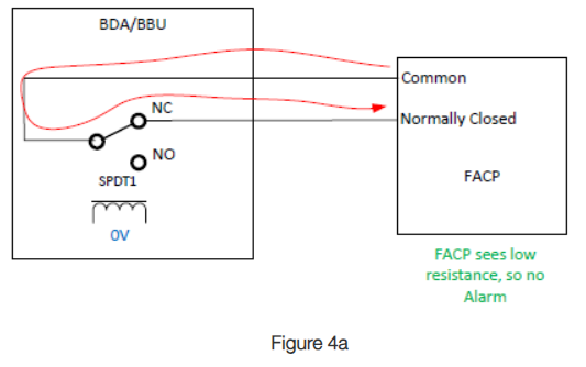
Figure 4b below shows a Normally Closed path (Energized Relay = Alarm) connected to an FACP. In this example, the circuit now has a “high resistance” or a “open” between the FACP and the BDA/BBU indicating an alarm has occurred.
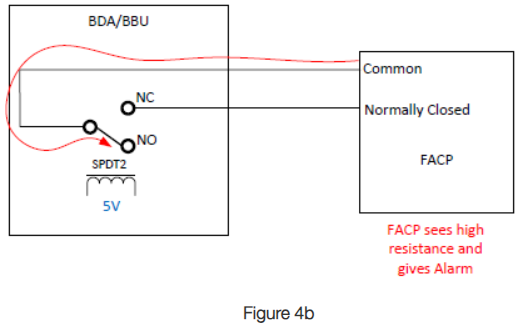
Figure 4c below shows a Normally Open path (Non-Energized Relay = No Alarm) connected to a FACP. In this example, the circuit has a “high resistance” or a “open” between the FACP and the BDA/BBU indicating no alarm.
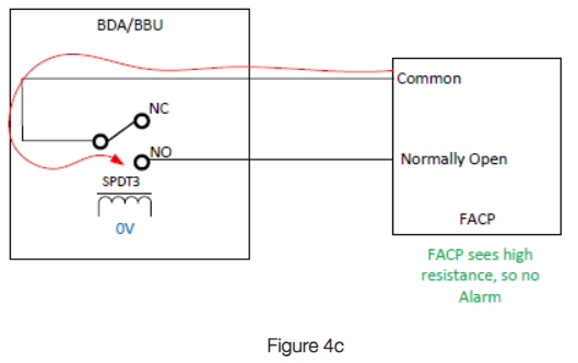
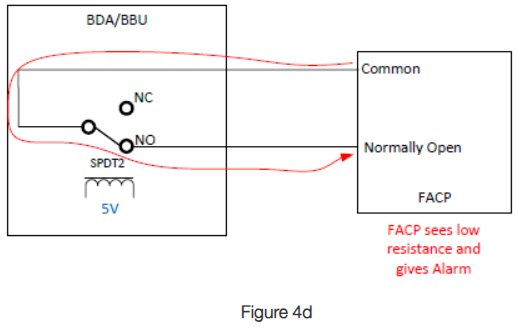
Figure 4d below shows a Normally Open path (Energized Relay = Alarm) connected to an FACP. In this example, the circuit now has a “low resistance” or a “short” between the FACP and the BDA/BBU indicating an alarm has occurred.
Normally Open Vs. Normally Closed with reference to an “non-energized” relay (device in alarm) and the Fire Alarm Control Panel (FACP):
NOTE – This is the preferred relay configuration, as when the active device, i.e.- BDA/BBU, loses power, the relay will de-energize and toggle, thus creating an alarm condition.
Figure 5a below shows a Normally Closed path (Energized Relay = No Alarm) connected to an FACP. In this example, the circuit has a “low resistance” or a “short” between the FACP and the BDA/BBU indicating no alarm.
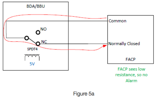
Figure 5b below shows a Normally Closed path (Non-Energized Relay = Alarm) connected to an FACP. In this example, the circuit now has a “high resistance” or a “open” between the FACP and the BDA/BBU indicating an alarm has occurred.
Figure 5b
Figure 5c below shows a Normally Open path (Energized Relay = No Alarm) connected to an FACP. In this example, the circuit has a “high resistance” or a “open” between the FACP and the BDA/BBU indicating no alarm.
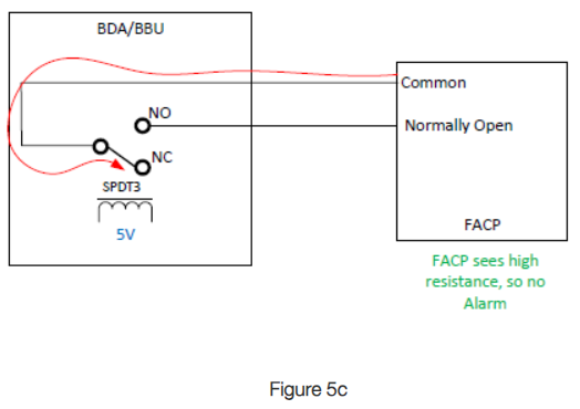
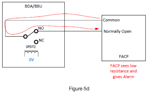
Figure 5d below shows a Normally Open path (Non-Energized Relay = Alarm) connected to an FACP. In this example, the circuit now has a “low resistance” or a “short” between the FACP and the BDA/BBU indicating an alarm has occurred.
End-of-Line Resistors – The End-of-Line (EOL) resistor completes the zone circuit in the Fire Alarm Control Panel (FACP) and are generally the responsibility of the fire alarm contractor.
For a typical FACP, the notification device (i.e.- BDA or BBU) signals can be either normally open (NO) or normally close (NC). The resistor completes the circuit for a small current to pass through and check the alarm state.
There are three possible scenarios involving EOL resistors:
- No voltage (wiring compromised and shorted) ~ 0VDC
- Fully open circuit voltage (wiring compromised and opened) ~ 12VDC
- Reduced voltage (closed circuit and secure) ~ 5VDC
In case of any error, the FACP will report the issue that circuit needs to be checked. For example, a 0V reading would indicate the alarm zone has been compromised and a short has occurred, thus creating a wiring fault alarm. A 12V reading would indicate the alarm zone has been compromised and an open circuit has occurred, thus creating a wiring fault alarm. A 5V reading would mean the zone is closed with the EOL resistor and no wiring fault is present.
Having the EOL resistor will ensure the farthest device, hence the word “end-of-line”, cannot be disabled by shorting the wire. The resistors are almost always used by the FACP because notification devices are normally open and close only upon tripping/activation.
Tools:
The most important tool when working with and connecting dry-contact alarms is a Volt-Ohm meter.
The Volt-Ohm meter has two very useful functions when checking for continuity:
- Ohms (resistance measurement) function
- Diode/continuity (open/short) function
When using the Ohm function on the Volt-Ohm meter, you are measuring the resistance of the circuit path, and looking for a “open” or “short” circuit. An “open” circuit will show up as “1” or “infinity” on the display, and a “short” circuit will show up as a “0” or very close to zero on the display.
When using the diode/continuity function on the Volt-Ohm meter, you are measuring an “open” or “short” circuit. An “open” circuit will be indicated by a “1” or “infinity” no audible beep, and a “short” circuit will show up as a “0” or close to zero with an audible beep.
When dealing with dry contacts, the diode/continuity function is the better option.
ALARMING COMBA EQUIPMENT:
CONNECTING THE COMBA BDA/FIBER BDA TO THE FACP (OR ANOTHER MANUFACTURES BBU)
The Comba BDA/Fiber BDA will provide the system integrator with four to six dry-contact alarms, please reference the Comba user manual specific to the signal booster being installed for wiring outline details.
Each alarm will consist of three wires or connections points, Normally Closed (NC), Common, Normally Open (NO).
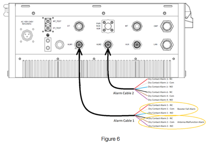
The two primary dry contact alarms of importance are shown below, the other dry contacts can be used as required per the Authority Having Jurisdiction (AHJ):
- Dry Contact 1 – Booster Fail Alarm (BDA Fault)
o NC – Opens when alarm occurs
o Common
o NO – Closes when alarm occurs
- Dry Contact 2 – Antenna Malfunction Alarm (Donor Antenna/Coax Fault/DAS VSWR)
o NC – Opens when alarm occurs
o Common
o NO – Closes when alarm occurs
The fire alarm contractor will advise as to what is required at the FACP. Based on this information, you will provide them with the following:
- The Common and NO leads = Which will close and produce a short circuit when an alarm occurs
- The Common and NC leads = Which will open and produce an open circuit when an alarm occurs
If EOL (End-of-Line) resistors are required, work with the fire alarm contractor or refer to the Comba user manual for instruction.
Examples of Comba BDA/Fiber BDA alarming wiring connections, using the included alarm cables:
- ½ Watt and 2-Watt BDA, Figure 6 below
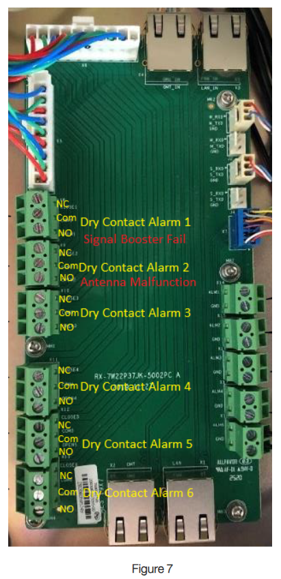
5-Watt BDA (No alarm cable/s provided, the System Integrator must hardwire connections between the 5-Watt BDA enclosure circuit board and BBU enclosure), Figure 7 below
700/800 Fiber DAS, using the included alarm cables Figure 8a and 8b below
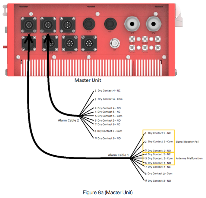
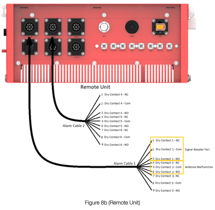
CONNECTING THE COMBA BDA/FIBER BDA TO THE COMBA BBU (V1 OR V2)
Connecting the Comba BDA/Fiber BDA dry contact leads to the Comba BBU is very straight forward. First you will determine the dry contact leads as shown in “Connecting the Comba BDA/Fiber BDA to the FACP (or another manufactures BBU)” above. These dry contact leads will then be connected to the External Inputs of the BBU located on the BBU Master Control Unit circuit board and labeled EXT1/EXT2/EXT3/EXT4.
External Inputs 1 and 2 are defaulted as Signal Booster Fail and Antenna Malfunction in the BBU.
The BBU External Inputs are looking for a “High” = NO or “Low” = NC in reference to ground of the BBU.
Typically, the NO/Com circuit of the BDA/Fiber BDA is connected to the External Inputs, thus the BBU will be looking for a “Low” to indicate an alarm has occurred in the device being monitored. Please reference figure 9 below for the logical wiring diagram.
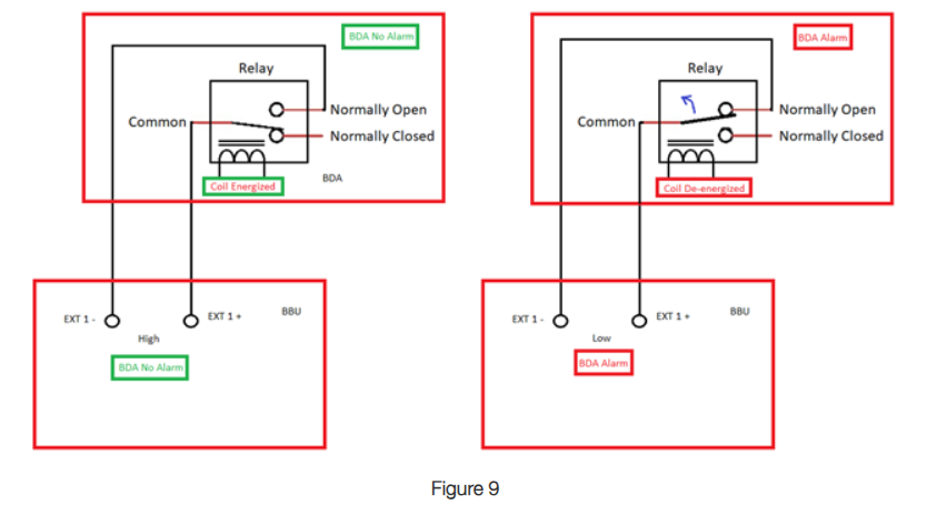
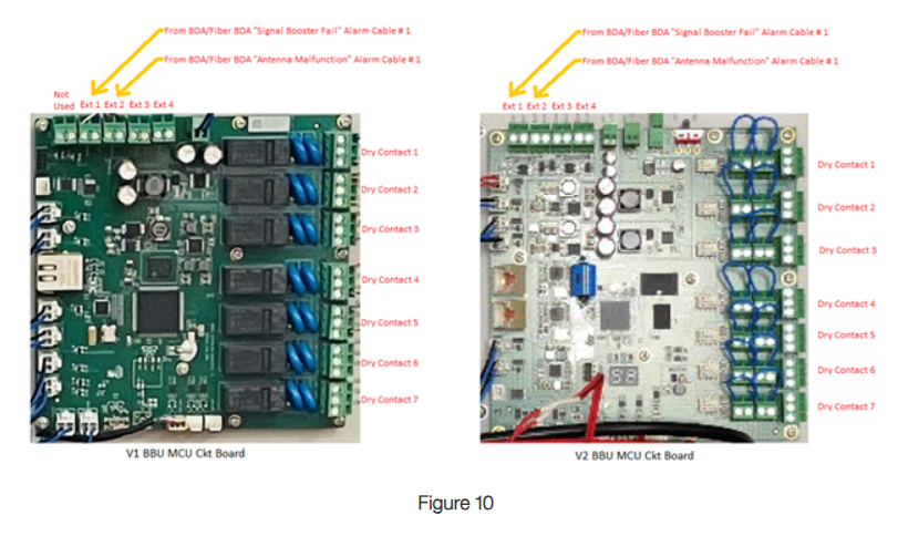
Figure 10 below identifies the External Input location and connection points on the Comba BBU V1 and V2 Master Control Unit circuit boards.
CONNECTING THE COMBA BBU (V1 OR V2) TO THE FIRE ALARM CONTROL PANEL
Once the BDA/Fiber BDA is connected to the BBU External Inputs (1 & 2), the next step is connecting the dry contacts of the BBU to the building Fire Alarm Control Panel (FACP).
The FACP External Inputs, like the BBU External Inputs 1 thru 4, are looking for a “high” or “low” to determine if a fault has occurred in the device(s) being monitored (BDA/Fiber BDA and BBU).
In this case, the FACP will require the minimum* of the five National Fire Protection Agency (NFPA) alarms listed below. *NOTE: The local AHJ may require more than the five alarms, if that is the case, this is when the BBU External Inputs 3 and 4 will be utilized and passed through the BBU to the FACP.
- AC Power Fail – From the BBU
- Battery Low – From the BBU
- Charger Fail – From the BBU
- Signal Booster/RF Emitting Device Fail – From the BDA/Fiber BDA (BBU EXT 1 Input)
- Donor/Antenna Malfunction – From the BDA/Fiber BDA (BBU EXT 2 Input)
- *System Component Malfunction/User Definable – From External Source (BBU EXT 3 Input)
- *Donor Antenna Disconnect/User Definable – From External Source (BBU EXT 4 Input)
The BBU has seven sets of dry contact alarms, and each alarm set will have a NO, Common, and NC terminal.
The Fire Alarm/Low Voltage contractor will advise if the FACP requires a NO/Com or NC/Com connection pair.
Figure 11 below shows the location of the seven dry contact terminals on the Comba BBU V1 and V2 Master Control Unit circuit boards.
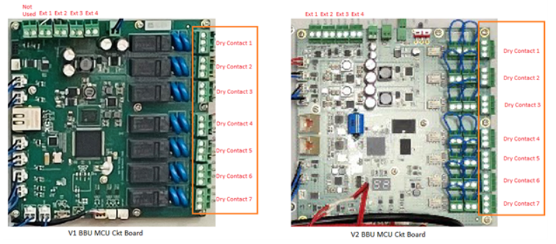
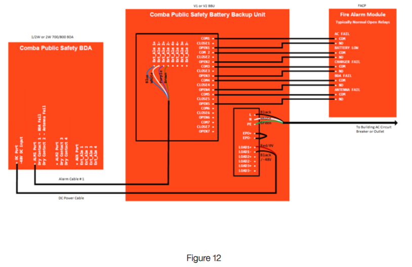
Figure 11 Figure 12 below shows an example of a fully wired BDA/BBU/FACP diagram for reference.
CONNECTING COMBA ANNUNCIATOR PANEL (AP) TO FIRE ALARM CONTROL PANEL (FACP)
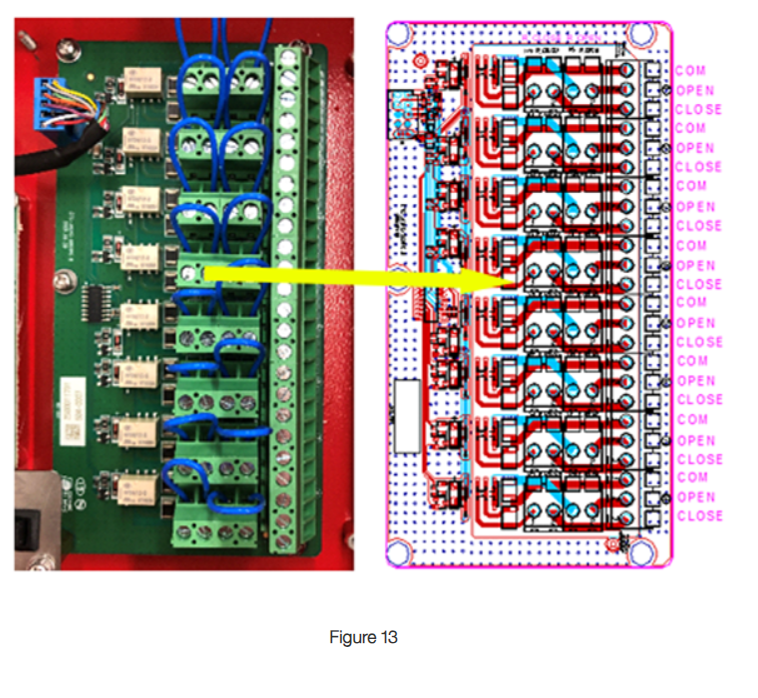
When connecting the FACP to the AP, the connection points are on the phoenix connectors on the right-hand side of the panel. Every 3 connectors are 1 set. Alarm 1 starts at the top and Alarm 8 is at the bottom. NC or NO can be used for each alarm set. Both cannot be used at the same time per set. In other words, NO and NC can’t be used on alarm 1, however, NO can be used on alarm 1 and NC used on alarm 2. NO is the common setup used. Wiring method will depend on alarming company and their requirements.
CONNECTING COMBA BBU TO NON-COMBA PA
- Same as “Connecting the Comba BBU (V1 or V2) to the Fire Alarm Control Panel” above.
- The AP can be powered from the BBU.
- BBU V1 48VDC only.
- BBU V2 can provide 12VDC, 24VDC, or 48VDC.
GUI ALARMING
ADDING IN ADDITIONAL ALARMS FROM THE BDA:
UHF BDA
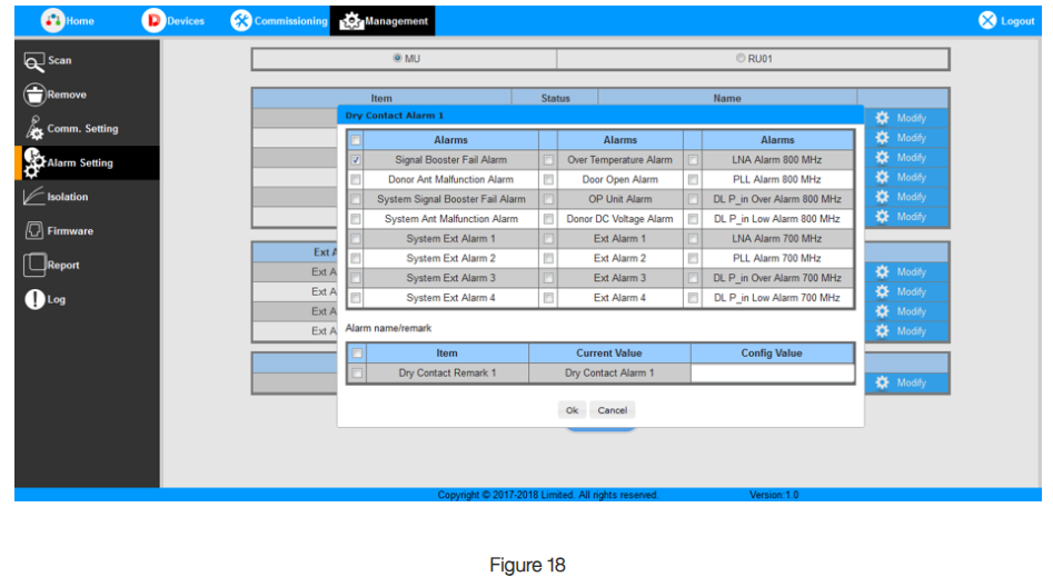
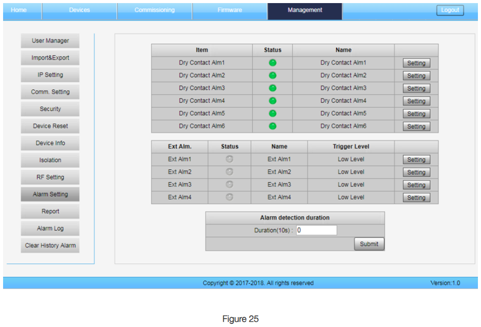
Click on the “Management” tab on the top of the screen and then click “Alarm settings” on the left-hand side of the screen to bring up the alarm settings.
From this menu, click “Setting” next to the Dry Contact you wish to edit/setup.
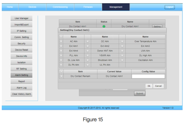
You can select whatever alarms you want to trigger that dry contact as well as change the dry contact’s name.
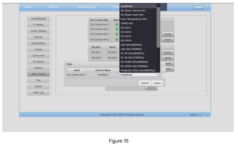
700/800 ½-Watt & 2Watt BDA
Click on the “Management” tab on the top of the screen and then click “Alarm settings on the left-hand side of the screen to bring up the alarm settings.
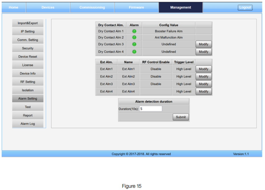
For this series of BDAs, only Dry Contacts 3 & 4 can be edited. Dry Contact 1 is pre-set to Booster Failure (any alarm will trigger this, including powering off the BDA) and Dry Contact 2 is pre-set to Ant Malfunction (The trigger from this is configured from the “Devices” tab). Additionally, only 1 alarm is programmable per dry contact for 3 & 4.
Fiber BDA
Click on the “Home” button in the top left corner of the screen. Then, select “Management”. After that, click on “Alarm Settings” on the left-hand side of the screen. From here, you can edit the MU or RU unit alarm settings you wish to trigger from each dry contact.
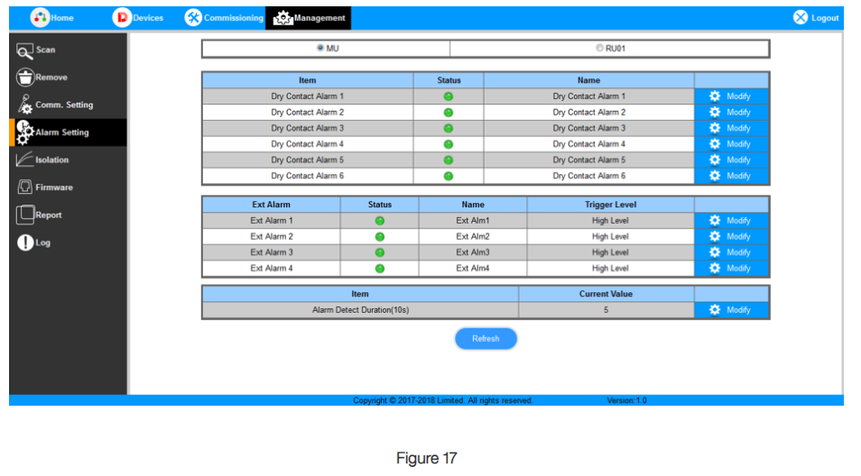
Click “Modify” next to the alarm you wish to change.
EDITING ANTENNA ALARM SETTINGS
UHF BDA
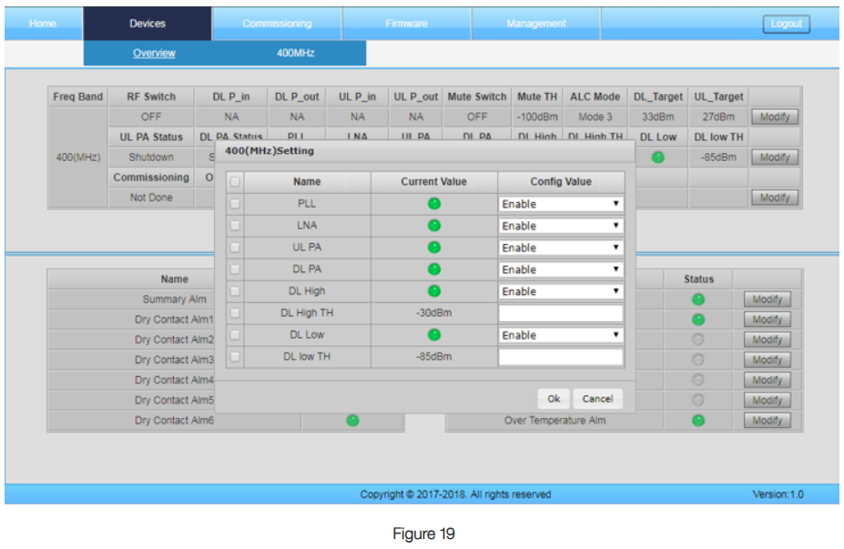
Click on the “Device” tab to edit the antenna alarm settings.
The second Modify button allows you to adjust your “DL Low” and “DL High” alarms. If using a Bias T, disable the “DL Low” alarm here.
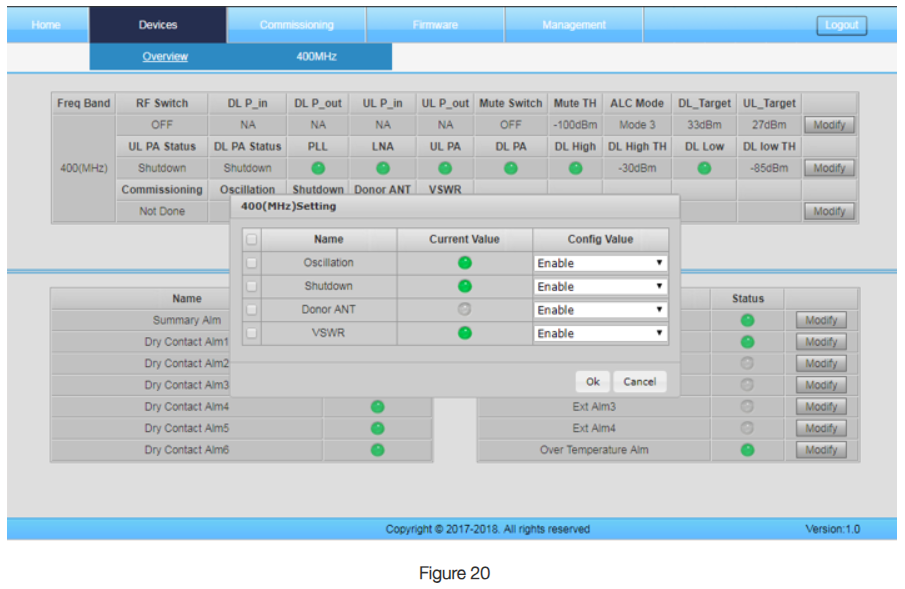
The third modify button allows you to turn on and off “Oscillation”, “Shutdown”, “Donor ANT”, and “VSWR” monitoring. By default, “Donor ANT” is off. This is only used when there is no control channel and a Bias T is needed.
Note: If Oscillation Detection is needed, contact Comba Customer Support for additional steps needed for setup
700/800 ½-Watt & 2Watt BDA
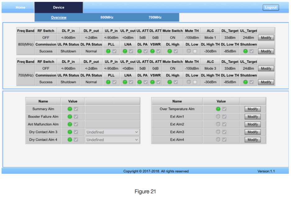
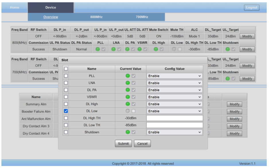
Under the “Device” tab, click “Modify” for each RF switch to change what triggers the Antenna Malfunction Alarm. DL Low is set off by default. This can be turned on by checking the box next to “DL Low” and making sure “Enable” is also selected. VSWR will also trigger the Antenna Malfunction alarm and can be turned on or off here as well.
Fiber BDA
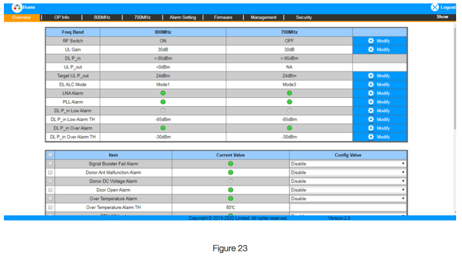
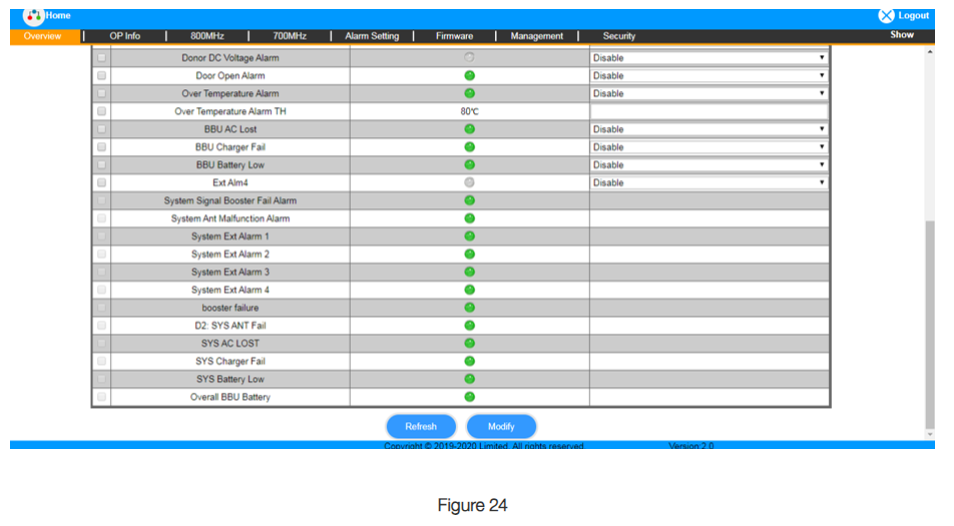
For the Fiber DAS, navigate to the “Overview” page on the unit you wish to modify. Figure 23 & 24 contains screenshots from the MU. Donor monitoring is off by default and can be turned on, on the MU. For when a control channel is present, turn on “DL P_in Low Alarm” for the associated frequency range. For when no control channel is present and a Bias T is used, turn on “Donor DC Voltage Alarm”.
EXTERNAL ALARMS
For External Alarms, or alarms you want to trigger in the BDA from external sources, you edit the settings for “Ext Alm#”.
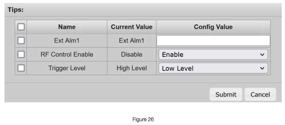
“RF Control Enable” will allow the RF to be switched off from the external alarm if triggered. This is only on Ext Alm 1-3. Ext Alm4 does not have this option to control the RF switch.
“Trigger Level” switches between NO and NC
Low Level = NO
High Level = NC
BBU EXTERNAL ALARMS
BBU external alarms are alarms coming from devices other than the BBU itself, for the BBU to monitor. An example of this is an alarm coming from the BDA.
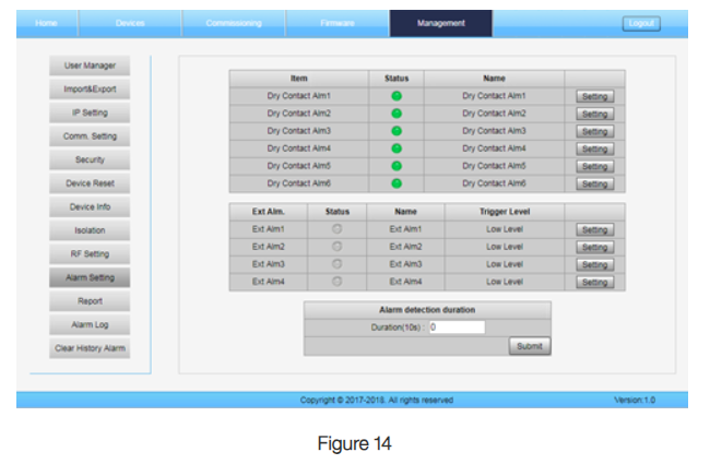
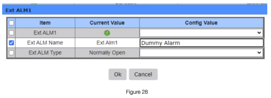
In the BBU GUI, navigate to the “Alarm Setting” tab. From here, click the external alarm you wish to modify.
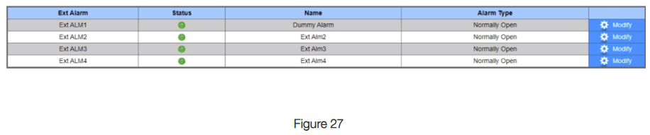
From here, you can edit if the alarm is monitored, alarm name, and if the relay is NO or NC. By default, these alarms are all on and set to NO.
BDA EPO SWITCH
The BDA EPO Switch can be installed using the External Alarms to trigger an electronic switch inside the BDA to turn off the amplifiers. The amplifiers will be off until the BDA EPO switch is turned back off. Check with your AHJ to see if this is needed.
ANTENNA MONITORING
There are four options to antenna monitoring, two on the DT port and two on the MT port, each for a specific application, pending which unit you have. For the DT port, there is DL_P in Low and Donor DC Voltage Alarm/ Donor Antenna Monitoring (name will vary pending which unit you have). For the MT port, there is VSWR and use of a Bias T (limited according to manufacture specs of Bias T and cable length). Each one of these options have different limitations.
NOTE: The ½ & 2W BDAs do not have Donor Antenna Alarm as a normal alarm and will need to make a custom External Alarm for monitoring.
Donor Antenna Monitoring
DL_P in Low is only usable when there is a control channel present. This monitors when there is a loss of the control channel, normally indicating a problem with the donor antenna or cable. This is off by default on the ½ & 2 W BDAs and Fiber DAS. For the UHF and 5W BDAs, this function is on by default.
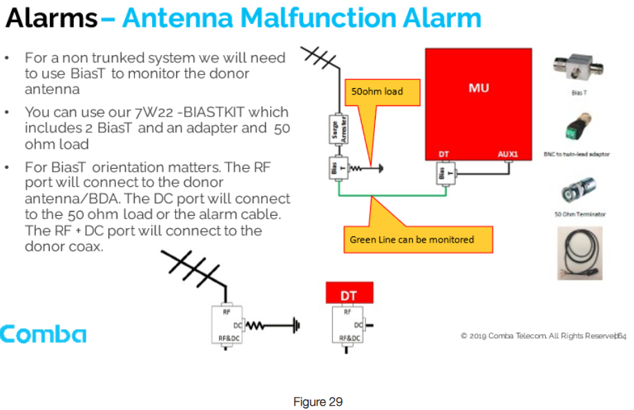
Donor Ant Alarm uses the Bias T kit to monitor the integrity of the cable and donor antenna to determine the functionality of the donor side of the system. On all units, this is off by default. After the Bias T kit has been installed, you must turn off “DL_P in Low alm” and turn on “Donor Antenna Monitoring”, under the Overview tab.
Passive DAS /MT Port Monitoring
VSWR – The VSWR alarm can be used to monitor problems with the passive infrastructure starting from the cable connected directly to the MT port of the unit to the first passive device (usually a coupler or splitter). This alarm will trigger an “Antenna Malfunction Alarm”. This is on by default for all units.
Bias T – This can be installed similar to the same method as on the donor, except it would be on the MT port instead. The alarm would be triggered on the associated Ext Alm it is connected to. Additionally, Ext Alarm would be configured so “RF Control”, is Disable on Ext Alm 1-3. Ext Alm 4 does not have this extra option.
CONCLUSION:
Improper understanding of public safety equipment alarming requirements and how the associated alarms work on the equipment can be costly from a project budget perspective and emergency responder safety standpoint. Not all AHJs test the required alarms and rely solely on the system integrator knowledge and qualifications that the alarms will function if/when needed. Familiarizing yourself with the basics of alarming functions, and how a manufacturer’s equipment alarms operate, will set you up for success for the various scenarios integrators come across in the field for installation or troubleshooting.