Well, for starters, many municipalities have–or are in the process of adopting–code requiring reliable in-building Public Safety communications, which oftentimes calls for the use of a Bi-directional Amplifier (BDA). A BDA is designed to boost/amplify weak off-air signals and re-radiate them in-doors. While these devices work well at enhancing in-building coverage, they also amplify noise. Some regions of the US are experiencing explosive growth in BDA implementations, and consequently AHJ’s are forced to engage and protect their countywide systems from degradation resulting from BDA generated noise.
In this article we focus specifically on the Uplink path. The downlink path generally has sufficient Signal-to-Noise ratio to ensure quality communications between Public Safety Base and Portables. There are, however, some cases where downlink noise may have a similar desensing effect in applications where both commercial and Public Safety DAS coexist. A discussion of this issue and how to mitigate can be found in the “The Mechanics of Colocation Filters” tech brief article published April 2018 on the Comba Website.
Here’s why AHJs are becoming hyperaware of the impact BDA’s have on their donor noise floor. Let’s start by defining how site noise floor fits into the bigger picture. Site noise can vary depending on the ambient RF environment. For example, in a rural setting where the only antenna on the tower is the Public Safety base station antenna, it’s possible that the receive sensitivity of the site could approach the thermal noise floor (kTB) plus some Noise Figure (NF) value applicable to the receiver equipment used. Let’s consider the kTB noise power of a 12.5 KHz channel to be -133dBm, which is the absolute theoretical best noise floor that can exist for that bandwidth signal. And then apply a NF of 6dB that represents noise added by the receiver equipment. Now we have a new noise floor of -127dBm (-133dBm + 6dB = -127dBm). A minimum signal strength from a distance portable or mobile should be at least 17dB above this noise floor, also known as the Signal-to-Noise Ratio (SNR). A SNR of 17dB generally results in a Delivered Audio Quality (DAQ) of 3.0; a minimum design parameter used in national codes and many local codes as it relates to Emergency Responder Radio Coverage Systems (ERRCS).
Consider the hypothetical example where a mobile radio 20 miles from the Donor Site was communicating just fine with a signal level of -110dBm (17dB SNR) into the donor site, or at least until a new BDA installation approximately 2 miles from the donor site raised the noise floor by 6dB. This 6dB rise in noise will deteriorate the mobile’s SNR down to 11dB, and consequently, clear intelligible communications between the mobile and donor site no longer exists. The mobile must reduce its path loss by 6dB to recover from the degradation induced by the BDA. If you’ve ever calculated a link budget then you know that free-space power loss is inversely proportional to the square of the distance, meaning that the mobile radio must move to a distance within 10 miles of the donor site to reestablish a SNR of 17dB and DAQ of 3.0. In short, all those First Responders operating in the radius zone between 10 miles out to 20 miles will have their communications either mildly, or in some cases severely, affected by a single BDA that was improperly installed.
Noise in the Real World
In the example above, we used a rural setting with an ideal noise floor which rarely exists. Now it’s time to get real. Most Public Safety in-building code requires a minimum signal level of -95dBm into the donor site’s receiver frontend and an SNR of 17dBm minimum. A 17dB SNR would suggest a site noise floor of -112dBm. This -112dBm noise floor value does in fact align closely with “real world” site noise levels prevalent in RF congested urban environments.
Matching Site Noise
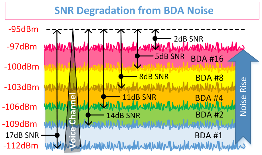
Let’s examine a case where a Class B (broadband) BDA is commissioned to match the Donor site noise floor of -112dBm. Did you know that tweaking the BDA gain to match the site noise floor will actually raise the site noise by 3dB? In the following graphic we show BDA#1 noise has been adjusted to match the -112dBm site noise floor and consequently we see a noise rise of 3dB at the site. A portable trying to communicate over a voice channel some distance away will experience a 3dB hit to its SNR, reducing a once acceptable 17dB SNR down to 14dBm. Now let’s look at the impact that 16 Class B BDAs have on site noise if all were optimized to match initial noise floor value of -112dBm. Every time we double the number of BDAs, we also double the noise contribution. Consequently, in this example, 16 BDAs will have a seriously detrimental effect on site performance. As more and more BDA’s are installed within the vicinity of the Donor site, it becomes very clear why AHJs are getting involved and holding system integrators to a higher standard.
Going 15dB Better
The following is an actual scenario where the AHJ must review and approve your link budget before turning up BDA. In this region of the US, code requires that noise generated by the BDA must be attenuated to 15dB below site noise floor of -115dBm. To comply, the commissioning engineer will work with the AHJ to ensure no degradation occurs at the donor site once the BDA is turned on. Since it is not possible to measure noise levels below site noise floor, the AHJ will expect BDA gain and power settings to closely match theoretical values submitted with link budget.
Why is it so important that BDA noise is 15dB below site noise? Simple. In-band Noise is additive as shown in the graphic above. If 16 BDAs (Class B) where installed at various distances from a Donor Site and all sites were perfectly optimized such that their noise levels arriving at the Donor Site were adjusted down to -130dBm, then the composite noise contribution from all 16 BDAs is actually -118dBm (10*log(16 BDAs)+(-130dBm)=-118dBm). This still seems acceptable right? After all, we are still 3 dB below the donor site noise floor. Now consider the case where we have 30, or 40, or 80 BDA’s? Is it conceivable that a Donor Site will serve 80 BDAs? The answer is yes. It’s happening now, and the number of BDA implementations will continue to rise because of code mandates.
Let’s use an actual scenario from a large metro area system and run the math for 80 BDAs: 10*LOG(80 BDAs) = 19dB. If we add the 19dB of composite noise contribution from 80 BDAs to the -130dBm noise floor that each individual BDAs was setup for, then we get -130dBm +19dB = -111dBm, which will certainly get the AHJ’s attention as their site Noise Floor has now increased by 4dB. As previously stated, any impact to the donor site noise floor will adversely affect its greater coverage area.
Class A or Class B?
Which Class of BDA has the least impact on the Donor Site noise floor? The answer is a resounding “Class A” and here’s why. Most Class A BDAs on the market today utilize digital technology with sharp filters designed to pass only desired frequencies. One benefit Class A offers in addition to sharp filter characteristics is that they generally have a squelch threshold where the channel remains quiet until a sufficiently strong signal is detected. Conversely, in a broadband device, such as Class B BDA, all frequencies within a set passband are transmitted continuously. What this means is that the Class B BDA is amplifying and transmitting noise continuously.
Let’s run through a simplified link budget to compare and understand this point.
Assumptions:
- Distance from Donor Site to Serving Site = 2 miles.
- Total path loss between sites including antenna gains and cable losses = 90dB
- Donor Site Noise Floor as stipulated by local AHJ code: -115dBm/12.5KHz
- Serving Site Noise Floor as stipulated by local AHJ code: -115dBm/12.5KHz
Class B – Uplink Link budget
-115dBm Serving Site noise floor @ 12.5KHz bandwidth (taken from code)
+90dBm BDA set at full gain
+ 5dB BDA Noise Figure
-90dBm Total Path loss
-110dBm Noise Floor arriving at input of Donor site receive equipment
-(-130dBm) Noise Floor required by Code (15dB lower than Donor Site noise floor)
20dB Amount of additional noise suppression needed to comply with code
Class A – Uplink Link budget
-115dBm Serving Site noise floor @ 12.5KHz bandwidth
+60dBm* BDA set to 90dB gain and no traffic. Channel is squelched.
+ 5dB BDA Noise Figure
-90dBm Total Path loss
-133dBm Noise Floor arriving at input of Donor site receive equipment: -115+60+5-90= -140dBm, however this level is below the theoretical best and therefore we default to -133dBm value for 12.5KHz
-(-130dBm) Noise Floor required by Code (15dB lower than Donor Site noise floor)
0dB Amount of additional noise suppression needed to comply with code.
*Even though a channel might be squelched, some noise is created by the DSP process and amplified by the uplink wideband Power Amplifier of BDA. A Class A device produces 20-40dB less in-band noise than a Class B device. In this example we use 30dB as the noise improvement over Class B
One caveat regarding the above calculation is that FCC allows up to 75KHz window filters for Class A devices. Depending on the bandwidth of the channel filter and how sharp it’s roll-off, some noise rise may occur at adjacent channels.
Resounding Just Got Better
While there is no argument that Class A devices are the better choice for throttling back in-band noise, is it enough? In the example above, we demonstrated how the Class A device generates approximately 30dB less noise than the Class B device. Wouldn’t it be ideal if during that 99% of the time when a BDA sits idle waiting to serve our First Responders, that it generate no noise whatsoever, ZERO NOISE?
In true innovative character, Comba has recently added several improvements to our CriticalPoint™ Public Safety product line, to include this ideal ZERO NOISE quieting feature. Contact your local Sales Manager or Comba USA in Milpitas CA for more details on this feature and many others.