With Comba Telecom’s 5W CriticalPoint Public Safety BDA now available, we decided to take a look at the use cases of when to use a 5W BDA and when to stick with a fiber DAS.
With Comba Telecom’s 5W CriticalPoint Public Safety BDA now available, we need to look more closely at the use cases of when to use a 5W BDA and when to stick with a fiber DAS. We have already gone through campus applications (https://combausa.com/en/tech-briefs/why-a-fiber-das-is-better-than-individual-bdas-for-campus-applications) and looked at why we should use a fiber DAS when a single building requires more than just a single BDA (https://combausa.com/en/tech-briefs/choosing-between-fiber-das-and-individual-bdas-for-large-building-applications). Comba only had a 2W BDA and a 2W Fiber Remote unit to offer when the large building application was written. Now that Comba has a 5W BDA and still has a 2W Fiber Remote, we will look at when to use one 5W BDA vs. two 2W Fiber Remotes.
Starting with the most important question, let us first look at cost. This answer is simple: A 5W BDA and battery backup costs less than a fiber DAS with 2 remotes and appropriate battery backup.
5W BDA | Fiber DAS | ||
Item | Quantity | Item | Quantity |
5W BDA | 1 | Master Unit | 1 |
100 AH BBU | 1 | Remote Unit | 2 |
|
| 55 AH BBU | 1 |
|
| 100 AH BBU | 1 |
|
| Fiber + Enclosures | 1 |
Total Cost | $ | Total Cost | $$ |
The cost for a fiber DAS, which includes the master unit, remote units, battery backups, and fiber is approximately twice the cost of a single 5W BDA and battery backup. Please contact Comba for exact pricing, but the point to be made here is that we want to install a 5W BDA when possible. We will keep this in mind for each of the following scenarios. Comba disclaimer: the following scenarios are talking about achieving a -95dBm downlink coverage level only. When designing, keep in mind all other requirements for your jurisdiction, including DAQ, dominance over native signal, and uplink signal strength requirements. These requirements may change how you need to design the system.
Before diving too deep, let us quickly review the equipment we are comparing and what type of building we are working with. Comba’s 5W BDA has an output power of 5W, or 37dBm, per band. Comba’s Public Safety Fiber DAS has 2W remote units, with an output power of 2W, or 33dBm, per band. When deploying 2 remote units, you have a total composite output power of 4W, or 36dBm per band. This means that a fiber DAS with 2 remotes has less total RF output power, however, a fiber DAS with 2 remotes will typically cover more area. The typical building where we would compare when to use a 5W BDA or a fiber DAS is going to be 400,000 to 900,000 square feet (this depends on building density, channel count, local requirements, constructability, and more). In these scenarios, two fiber remotes would be located anywhere from 100 to 400 feet away from each other. At 100 feet, ½” coaxial cable has about 2.25dB of loss at 700 and 800MHz frequencies, so you lose the extra power to cable loss.
TALL BUILDING
For this example, we will look at a 40-story tall building, with approximately equal sized floors. The total square footage is about 800,000 square feet, with about 20,000 square feet per floor.
To summarize, if you have a building that a 5W BDA will cover if conveniently placed, you can substitute (2) 2W fiber remotes and cover the building as well. The more cost-effective solution is the 5W BDA, however, you may not have the option of placing the BDA where you want and designing the building so it works, and a good replacement is a 2 fiber remote solution.To summarize, if you have a building that a 5W BDA will cover if conveniently placed, you can substitute (2) 2W fiber remotes and cover the building as well. The more cost-effective solution is the 5W BDA, however, you may not have the option of placing the BDA where you want and designing the building so it works, and a good replacement is a 2 fiber remote solution.
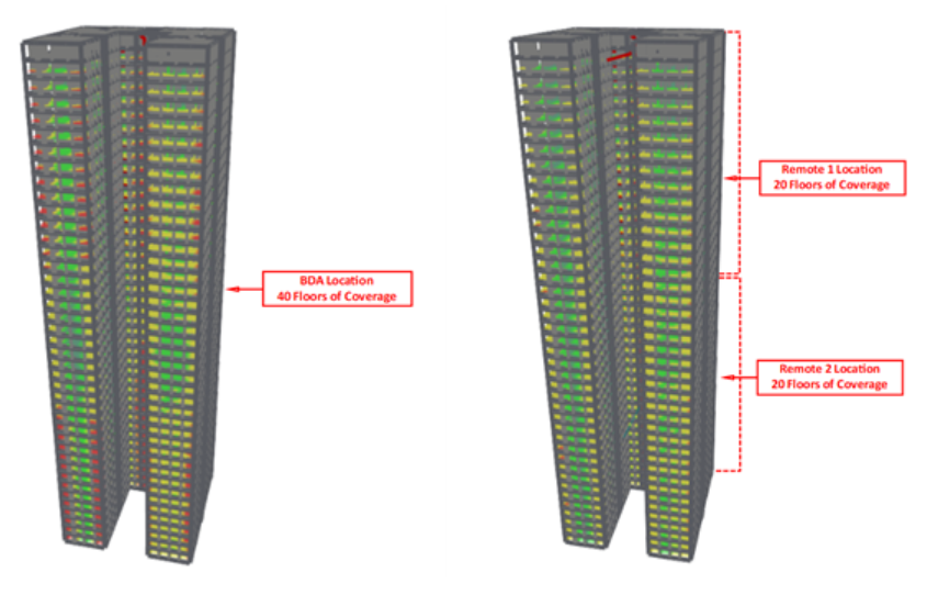
In the 5W BDA only scenario, we place the BDA on the 21st floor, and cover 20 floors up and 20 floors down. There are a few challenges to this design that could cause problems. First, the donor antenna cable run will be over 200 feet in the 5W BDA scenario. A link budget must be done to ensure you can get full output power and an appropriate signal strength back to the donor tower. Second, there must be a location to install the BDA at or near the 21st floor, and this location must comply with local code. Finally, the building must be constructed so you can have a continuous riser from the first to the top floor for service antennas, without a long riser run between floors.
The design calls for a minimum of a 40 foot antenna radius at -95 dBm, which, based on building density, means the input power to each antenna must be greater than -15.6 dBm. Note: All calculations are estimates done for the purpose of demonstration – your requirements may differ.
In the perfect scenario, we place the 5W BDA on the 20th or 21st floor, or put the 2W fiber remotes on the 10th and 30th floors. With a stacked riser closet, the 5W BDA has a total passive loss of about 38.7 dB to the service antennas. In the 2W fiber remote scenario, there is about 30.5 dB of loss to each antenna.
| 5W BDA, Ideal Installation | 2W Fiber Remotes, Ideal Installation |
Output Power, Total (dBm) | 37 | 33 |
Number of Channels | 15 | 15 |
Power per Channel (dBm) | 25.2 | 21.2 |
Loss to Antenna (dB) | 38.7 | 30.5 |
Antenna Output Power (dBm) | -13.5 | -9.3 |
Coverage Radius @ -95dBm, 3.7 VPLE with 8dB margin | 45 | 59 |
Both cases will work to cover the full building, which is great – you can take your pick of which system to install, and based on cost, the best choice here is going to be the 5W BDA.
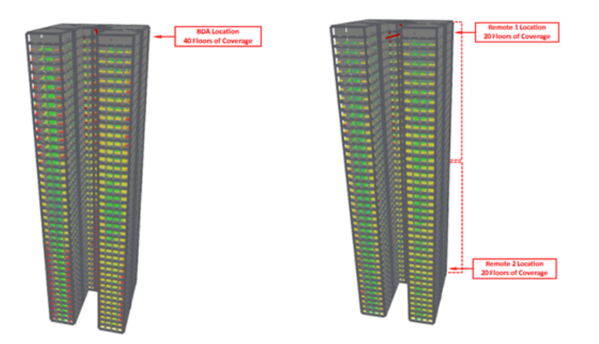
Now we will look at non-ideal scenarios for equipment location. A common situation is that the BDA is installed on the very bottom or very top floor, based on space restrictions. A donor antenna cable run of over 500 feet is not ideal, so we will assume in the worst case, the BDA will go on the top floor. In a similar scenario, the worst case for fiber will be the top and bottom floors for equipment locations.
| 5W BDA, Top Floor Installation | 2W Fiber Remotes, Top & Bottom |
Output Power, Total (dBm) | 37 | 33 |
Number of Channels | 15 | 15 |
Power per Channel (dBm) | 25.2 | 21.2 |
Loss to Antenna (dB) | 43.9 | 34.2 |
Antenna Output Power (dBm) | -18.7 | -13.0 |
Coverage Radius @ -95dBm, 3.7 VPLE with 8dB margin | 33 | 47 |
While the fiber system will still cover the building, the 5W BDA is no longer able to provide adequate coverage, so we would have to use a fiber system in this building. Always be sure that you confirm the equipment mounting location before starting a design or submitting a bid – it can change the required equipment dramatically!
SHORT BUILDING WITH A LARGE FOOTPRINT
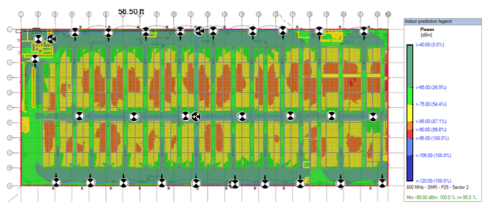
For the next scenario to compare, we will look at a warehouse style building. This building will be one level tall and a 634,400 square feet (1,220 feet long by 520 feet wide). In this building, we will have tall shelving units with walking aisles between them. Once again, we must make the disclaimer that every building is different, so bid based on your building and local requirements.
Since we have already stated that a 5W BDA will be a less expensive install, we first design based on a 5W BDA. The BDA is centrally located, with directional antennas on the outsides of the building and omni antennas in the middle. Running the predictions in your RF propagation software, we have plenty of signal strength and will pass our -95dBm requirement with margin to spare:
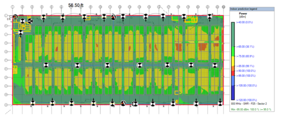
If we are bidding this project, however, we cannot assume that the BDA will be able to be located in the middle of the building. What happens with this same design, but instead of putting the BDA in the middle of the building, we must put it in the corner, near where the FACP is located?
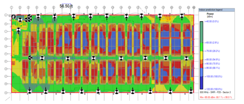
In the “worst case BDA location” situation, the building fails. The reason is simple – the long cable run adds extra loss, leading to a system you can’t balance and lower overall antenna output power. In the first scenario, with the BDA in the middle of the building, the antenna ERP/channel ranges from -5.66 dBm to -1.87 dBm. Using the exact same cable pathways, the antenna ERP/channel with the BDA in the corner of the building ranges from -18.20 to -8.09 dBm. We are losing anywhere from about 6 to 13 dBm output power at each antenna location.
To fix this issue, we can replace the BDA with a fiber DAS. We will still put the master unit in the required corner location, but now we can run fiber to any point in the building, so we pick two convenient locations and place the fiber remotes in the center, one at the top and one at the bottom. Running predictions, we can see that we improve in signal strength with 2 fiber remotes as compared to one 5W BDA:
To summarize, if you have a building that a 5W BDA will cover if conveniently placed, you can substitute (2) 2W fiber remotes and cover the building as well. The more cost-effective solution is the 5W BDA, however, you may not have the option of placing the BDA where you want and designing the building so it works, and a good replacement is a 2 fiber remote solution.