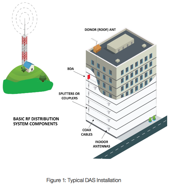
When looking to provide public safety coverage for a campus environment, it is important to look at the building configuration to determine if a fiber DAS solution will be required. With a typical BDA installation, one must have adequate off-air signal and an isolation of at least 20dB higher than the required gain. Figure 1 shows a typical BDA installation. With no other buildings nearby with a BDA, our system inputs and outputs are easily defined. The inputs are the downlink signal from the tower and the uplink signal from any radios within the building. The outputs are the downlink coverage inside the building and the uplink signal transmitted back to the donor tower.
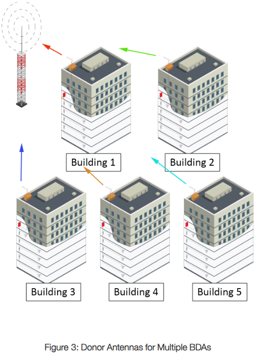
We will use an example of 5 buildings in a campus configuration to look into the challenges of both the multiple BDA scenario and a fiber DAS installation. Assuming there is a single donor tower, all Yagi antennas will point towards this tower in the multiple BDA scenario. In the fiber DAS scenario, there will be a single Yagi antenna that is on the building closest to the donor tower.
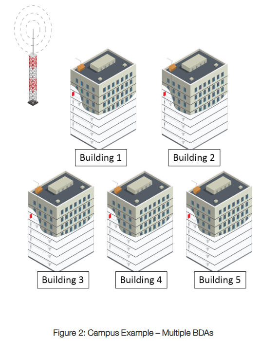
In this example, the Yagi antennas are all pointed towards the donor tower. However, as you can see, Building 1 is directly in the line of site path for Buildings 4 and 5, and indirectly in the line of site path for Building 2. (Note that each of the 5 buildings have their own BDA – more about that later). As you can see from Figure 2 above, only Building 1 and Building 3 have a true unobstructed line of site to the donor tower. The signals from Buildings 2, 4 and 5 passes over Building 1 before reaching the donor tower.
If the UL signal is strong enough and the path loss is low enough from Buildings 2, 4, or 5, the system in Building 1 could re-amplify the uplink signal from any of these buildings. This cascaded effect could become problematic by both causing multipath problems and increasing the noise floor. Let’s look at both examples.
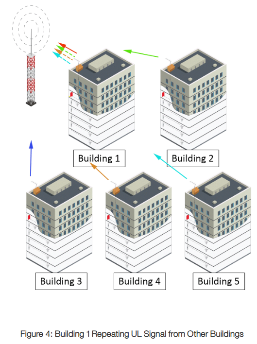
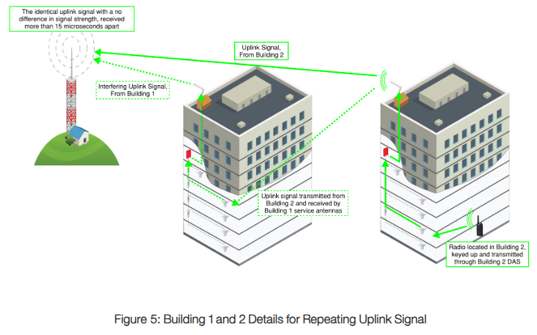
First, we will look into the signal strength that will be seen inside Building 1 when making an UL transmission from inside of Building 2:
UL Output from Building 2 BDA | 17 | dBm |
Yagi Antenna Gain Less Transmission Line Loss | 8 | dB |
Free Space Path Loss, 100 feet (+ Building Losses) | 68 | dB |
DAS Loss (Building 1) | 15 | dB |
Expected Building 1 BDA UL Input (from Building 2) | -58 | dBm |
UL Gain on Building 1 BDA | 75 | dB |
UL Output from Building 1 BDA | 17 | dBm |
In this scenario, an uplink transmission that leaves the Building 2 BDA at full power could possibly leave the Building 1 BDA at just the exact same signal strength, with the delay of the 2nd BDA added in. Depending on the system, this could cause multipath distortion and make it difficult or impossible to communicate. This is a textbook example of Time Delay Interference (TDI)!
There is a way to avoid this: while commissioning the BDA in Building 2, verify that the uplink signal at full power out of the Yagi antenna in Building 2 will be a minimum of 20dB less than the required power for maximum UL signal out of the BDA in Building 1, when measured at the input to Building 1’s BDA. This procedure must be repeated every time a new building is commissioned. If this procedure sounds complicated, imagine how complicated it would be once additional buildings are added into the mix. A cascaded effect could happen when adding another layer of buildings, so it is vital to system performance that any transmissions that are repeated by another building are below the tolerance of the radio system.
A better way to avoid this is to install the system as a fiber DAS – with only a single Yagi, provided the signal from the Yagi to the donor tower has no obstructions, there will be no UL multipath issues.
Note: -133 is thermal noise floor – Noise Floor cannot be below this. |
Now let’s take a look at the noise floor scenario for this same system.
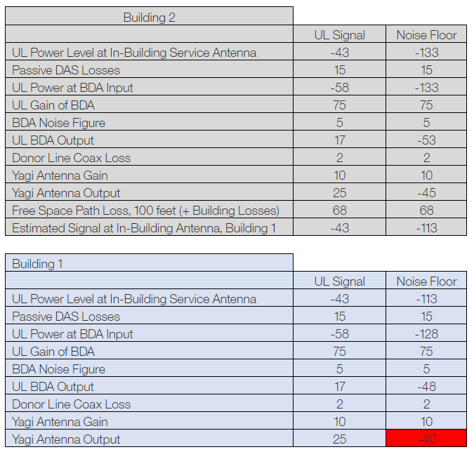
In the case above, the noise floor of the Building 1 BDA would rise based on the cascaded noise from the Building 2 system. Of course, there are ways to make sure this doesn’t happen, such as ensuring that each new system that is turned on does not cause an increase in the incoming noise floor of any other independent DAS on the campus. This can become tedious work, and while you can avoid having a raised noise input into your system, you can still have UL signal cause other types of destructive interference going into another building.
Now, imagine having multiple buildings in line with a Yagi antenna on the roof with a beamwidth wide enough to have clear line of site to at least one service antenna in the next building. The noise in this situation can quickly get out of hand – in the case above the noise floor rise was 5dB, with a third building in line this would increase to 10dB, and so on. With a fiber DAS scenario it is much easier to calculate noise floor rise – a simple expression of – and one can make sure this does not cause a problem by limiting the coverage area of each remote unit such that the UL signal will make it back to the donor site at an adequate signal level with additional attenuation at the head end location.
A fiber DAS that is correctly commissioned will not introduce any additional noise to the donor site, while a campus full of BDAs, even when each individual DAS is correctly commissioned, can very easily introduce a large noise floor rise to the donor site.
Now, let’s look at another scenario, this time based on a real-world problem that caused an issue with a county radio system and was subsequently fixed when it was discovered the adjacent building also contained a BDA:
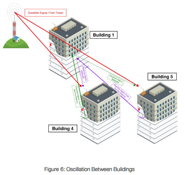
For this scenario, refer to figure 6 above. Let us consider a situation where the DL control channel signal strength of -70dBm is measured at the input to the BDA in each building. Our radio system has 20 channels. The DL gain in this example will be set to 90dB, and the isolation within each individual building is a minimum of 110dB.
DL Output of Service Antenna, Building 4 | 0 | dBm |
Path Loss to Building 1 and Reflected Back to Building 5 (250 feet) | 85 | dB |
Yagi Antenna Gain Less Transmission Line Loss, Building 5 | 8 | dB |
Measured DL Input to BDA at Building 5 (from Building 4 Service Antenna) | -77 | dBm |
In In the two building oscillation scenario, when commissioning Building 4, one must measure isolation of the Building 4 service antennas to donor, Building 4 donor to service antennas (as always), Building 4 service antennas to Building 5 donor, and Building 5 service antennas to Building 4 donor (and ensure this meets the minimum isolation requirements for the radio system). As you add buildings with individual BDAs, increasing care must be taken to measure isolation between each of the buildings.
the example, the input to the Building 5 BDA for the control channel will be -70dBm off air and -77dBm from the DAS in Building 4. Assuming this link budget is the same in the opposite direction, there will be oscillation between Buildings 4 and 5.
In the fiber DAS scenario, a simple isolation test at the master unit will validate your system isolation.
Let’s now look at the fiber DAS architecture:
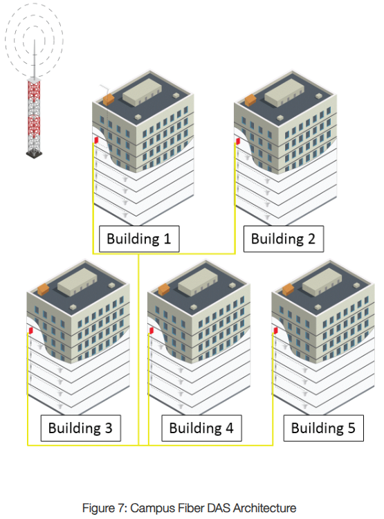
As previously stated, the noise floor rise is based on the number of remote units – you will get a rise in the noise floor at the master unit in Building 1. However, with no additional nearby BDAs, you can greatly minimize the risk of a cascaded noise floor increase or an uplink signal re-amplified with a time delay. There are cons to the fiber system, however: a single point of failure at the head end. If the master unit in Building 1 fails, the entire campus fails. This can be easily avoided by having an on-site spare available and closely monitoring the health of the system.
Besides the ease when commissioning the system to ensure proper behavior of all components, any future troubleshooting or system updates will be much easier and faster using a fiber DAS. With separate systems in all buildings, any donor tower changes, frequency changes, or system upgrades must be performed at each building separately (and then recommissioned if necessary, while ensuring all the scenarios previously discussed do not cause issues). With a fiber DAS, any updates are done at the head end only, greatly decreasing the time spent ensuring the system is running properly.
For a campus application, the clear choice is to deploy a fiber DAS to ensure your public safety radio network functions and provides all first responders with clear communication in every location on campus. There are many factors that go into choosing between fiber DAS and multiple BDAs. We have looked at a couple of examples for a campus, but a new set of issues may arise when covering a single large building or a train tunnel, such as the cascaded noise floor of multiple BDAs connected in line and the additional delay through each BDA. We will go into a deeper dive of these scenarios next time.