PART 5: A DEEPER DIVE INTO DESIGN CONSIDERATIONS
This section is meant to detail design considerations for your public safety system. It is not a comprehensive guide to design, only a guide for what to expect and consider when doing your design.
Comba has released multiple tech briefs in the past regarding preplanning public safety communication systems and code for rebroadcasting signals, and they should both be read for more information on planning your public safety design:
DESIGN TIP 1: UNDERSTAND YOUR JURISDICTION
Each jurisdiction throughout the country will have different requirements for ERRC Systems. The local code should describe minimum building size requirements for testing, failure criteria, frequencies required, battery backup requirements, system acceptance testing, and more. Codes are constantly changing and even if a national code is adopted, your local jurisdiction may make their own amendments to the national code.
IFC Section 510 and NFPA 1221 are the two most referenced codes when referring to in-building radio communication requirements. The IFC may be replaced with a state fire code. These are updated every 3 years and it usually takes time for the jurisdiction to adopt and enforce new code, so the AHJ will always be the best reference for what is actually required. In many cases, the AHJ will have their own code (ordinance) that incorporates excerpts from IFC Section 510, or NFPA 1221, or both – along with their own local electrical and building code requirements. And some cases, the local ordinance will incorporate excerpts from previous/older versions of IFC or NFPA guidelines.
There have also been cases where an integrator complied with the current published version of the local code – only to find out the hard way during the ATP that the AHJ had modified the code, was now enforcing the modified version – but had not yet made it publicly available in the current published version. So even though the system was fully compliant with the published code, the systems were failed by the AHJ until system changes were made.
Another example of undocumented changes – we have seen situations where the local code discloses the frequencies/channels to be covered. Then at ATP, it is discovered that the AHJ had added or changed channels since the published code document was created and had not yet been added to the published code. Again, the AHJ failed the ATP until the changes were made – and this can sometimes cos the integrator and/or building owner LOTS of money.
You must know your jurisdictional requirements for a proper design. It is highly encouraged that you obtain the published version of the local code, then talk with the AHJ to make certain that this is what they expect compliance with – or find out what has changed, so you can design accordingly. Verify the required coverage areas, verify the channels to be covered, verify the electrical requirements. Then you can be assured that your design is 100% compliant with what the AHJ will require.
DESIGN TIP 2: DESIGN A CONSTRUCTIBLE SYSTEM
The layout of the building is the next thing you must be familiar with before starting the design. Between nearby satellite imagery, floor plans, reflected ceiling plans, and building elevations, there should always be enough information to have a constructible design. The key parts of our public safety DAS are the donor antenna, BDA, and service antennas.
How to Locate the Donor Antenna
Your donor antenna should, if possible, have line of sight to the donor tower. Always consider the surrounding buildings, any geographical obstacles, and even the roof construction before choosing a final location for a donor antenna. If possible, see if you can find out about any expected new construction (i.e. a big building across the street) that could potentially ruin your clear line of sight to the tower. A cable pathway should be considered such that it complies with local codes and the cable length works with your link budget. Make sure that the cable is properly grounded.
Choosing the BDA Location
Ensure a proper room is chosen to house the BDA, battery backup (if required), and any other required system components. Depending on building size, the BDA might need to be strategically located in the center of the building to avoid requiring a higher power BDA or a fiber system, or the building may be small enough where the BDA location doesn’t matter at all. In the room you choose for the BDA, you could need some or all of the following:
- A cable pathway to the donor antenna
- Cable pathways to all service antennas
- AC power for either the battery backup or BDA
- A cable pathway to the FACP or annunciator panel for alarming
- Proper earth grounding
- Adequate mounting space and equipment clearance
- Required signage signifying there is a signal booster in the room
- An EPO switch
A good design will contain an exhaustive list of requirements and adhere to all of them.
Choosing Service Antenna Locations
Service antennas should be located strategically, usually in public spaces (for example, in a residential complex, antennas would be located in common areas such as hallways rather than in private units). Antenna density should be considered and will be discussed further below. Cable pathways must be feasible – for example, try to avoid pathways that require coring through concrete walls if there is an alternate going through wood framing. Some pathways will require survivability, whether this means conduit or 2-hour rated spaces – again, make sure you understand the local code and show on the design which cable pathways will require special consideration.
KNOW HOW TO DESIGN CLASS A VS. CLASS B
For a much deeper explanation into designing with Class A vs. Class B, read this tech brief: https://combausa.com/pr/class-a-vs-class-b/
For design purposes, the key takeaway from the tech brief are that a Class A BDA can be designed with a lower antenna density than a Class B BDA with similar results, ending up with a lower overall cost. It also incorporates channelized gain control, resulting in a lower noise impact on the donor tower.
SIGNAL STRENGTH PREDICTIONS
In iBwave, there are two common ways of modeling the signal strength: Fast Ray Tracing and Variable Path Loss Exponent. Fast Ray Tracing propagation modeling is a ray tracing algorithm that is used to predict in building signals. It considers the actual materials of the building and requires that the user creates a full 3D model of the building. Variable Path Loss Exponent uses a multiplier on the free space path loss equation to approximate the walls of the building without having to model the building entirely. With iBwave, there are ways to accurately and inaccurately use both of these propagation methods.
If using fast ray tracing, creating an accurate 3D model is important for accurate predictions. If using variable path loss exponent, it is important to know that these will not be perfect and you should build in a design margin to make up for unexpected extra losses (the author of this paper uses a 10dB design margin).
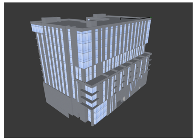
Sample 3D Building in iBwave with which you would use Fast Ray Tracing as your prediction model.
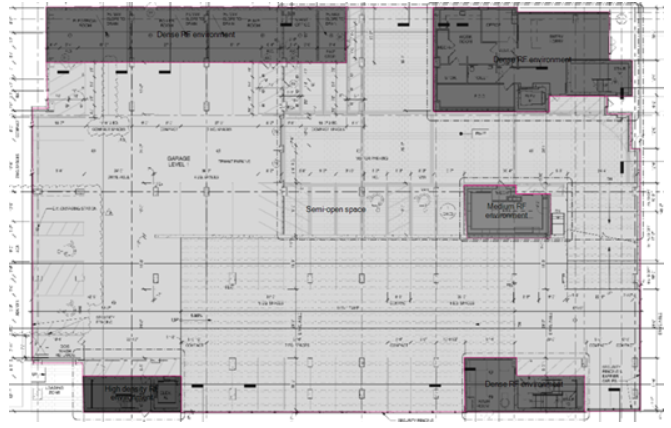
Sample floor plan of the same building in iBwave. Note that different areas of this floor are assigned different area types for separate variable path loss exponents.
Neither propagation model will ever give you completely accurate results (unless you use fast ray tracing and use model tuning) and you will need to take into account the time it takes to build an accurate 3D model versus the possible mistakes you could make with a variable path loss exponent.
CONCLUSION
- Come to the jobsite prepared with all tools you need to be successful
- Design the system for constructability
- Know your jurisdiction – code requirements (published and very new); know the contact people if you have questions
- Ensure adequate off-air signal
- Ensure adequate isolation
- Be ready to troubleshoot
- DO YOUR LINK BUDGET