OY-MN-V13P

758-869MHz, N-Female


Features:

• Covers the 758–869 MHz public safety band.
• Narrow beamwidth and high gain with 14-elements design
• Rated for high-wind environments up to 186 mph.
• Supports adjustable antenna tilt.
• Ideal for use as a donor antenna; constructed with anodized, welded aluminum.

Description

Electrical Specifications:


 Frequency (MHz) 758-869
 Gain (dBi)13
 PolarizationVertical
 Beamwidth Horizontal (°)35
 Beamwidth Vertical (°)32
 Average Power, max (W)300
 Impedance (ohm)50


Mechanical Specifications:


 Dimension Diameter, Height (in/mm)

54.3 x7.9x 2.0 / 1380x201x50

 Weight (lb/kg)6.1 / 2.75
 Shipping Dimension(in/mm)56.7x9.4x10.6 / 1440x240x270
 Shipping Weight(lb./kg)10.8 /4.9
 Radome Material & colorWhite Anodized, Welded Aluminum Finish
 Diameter of the pole mounting pole (in/mm) ∅1.8 - 3.0 / ∅45 - 75
 Antenna Tilt adjustment (°) ±15° max
 Maximum Wind Speed(mph) 186
 Connector type N-Female


Environmental Specifications:


 ApplicationOutdoor
 Operating Temperature -40°C to +70°C
 Relative Humidity Up to 95%
 RoHS Compliant
 Environment 
 Lightning Protection Direct Grounding
 

Antenna Pattern:


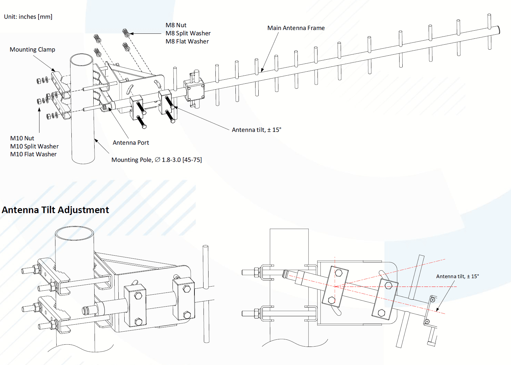
Mechanical Drawing & Installation Guide:


Installation Instruction:


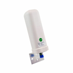
A. The main antenna frame is pre-installed with the mounting bracket, with vertical polarization set as the default.


B. Remove the M10 nut and the antenna mounting clamps, then place the antenna onto the mounting pole.


C. Insert the clamp, M10 washers, and M10 nut in order, and hand-tighten them to hold the antenna in place. Do not fully tighten the hardware until the final antenna orientation is confirmed. After the direction is set, fully tighten the M10 mounting nut.


D. To adjust the antenna’s tilt angle, slightly loosen the M8 nut on the antenna main frame assembly. Adjust the antenna to the desired tilt angle (maximum ±15°).


E. After setting the angle, tighten the M8 nut as shown in the drawing.


F. Connect the equipment and the antenna using the appropriate connectors.


G. Ensure all connections are waterproof. If necessary, apply a cold-shrink tube to seal the antenna connection. (Cold-shrink tube part number: CST-2806-125 or CST-2806-150)


H. Secure all antenna and equipment cables properly.


I. Position the cold-shrink tube to cover the antenna connector, then slowly pull out the inner core to release the pre-stretched tube. It will automatically contract and seal around the connection.


Datasheet:

OY-MN-V13P DS 1-0-0_2025_1113
 

This website uses cookies and similar technologies. By continuing to browse the site, you agreeing to our use of cookies. Read our Privacy Policy.

Continue